
3D Printed Artifacts under Tensile Loading
An Automated Design and Fabrication Pipeline for Improving the Strength of 3D Printed Artifacts under Tensile Loading
Can Mert Al1, a) and Ulas Yaman2, b)
1 Department of Test and Verification Engineering, TAI, Ankara, TURKEY
2 Department of Mechanical Engineering, Middle East Technical University, Ankara, TURKEY
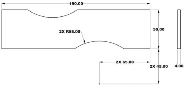
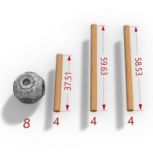
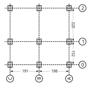
FIGURE 1. Dimensions of the Specimen Used for Testing (All dimensions are in mm)
In the scope of this study, an alternative automated method to the conventional design and fabrication pipeline of 3D printers is developed by using an integrated CAD/CAE/CAM approach. It increases the load-carrying capacity of the parts by constructing heterogeneous infill structures.
Traditional CAM software of Additive Manufacturing machinery starts with a design model in STL file format which only includes data about the outer boundary in the triangular mesh form. Depending on the given infill percentage, the algorithm running behind constructs the interior of the artifact by using homogeneous infill structures.
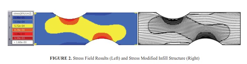
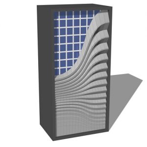
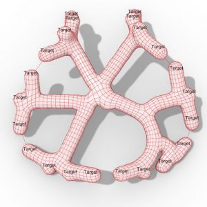
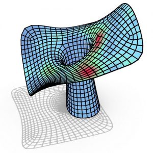
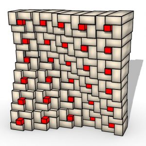
FIGURE 2. Stress Field Results (Left) and Stress Modified Infill Structure (Right)
As opposed to the current CAM software, the proposed method provides a way to construct heterogeneous infill structures with respect to the Von Misses stress field results obtained from a finite element analysis. Throughout the work, Rhinoceros3D is used for the design of the parts along with Grasshopper3D, an algorithmic design tool for Rhinoceros3D.
In addition, finite element analyses are performed using Karamba3D, a plug-in for Grasshopper3D. According to the results of the tensile tests, the method offers an improvement of load carrying capacity by about 50% compared to traditional slicing algorithms of 3D printing.
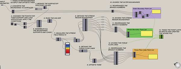
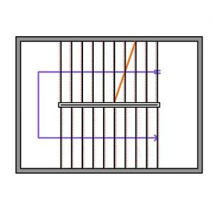
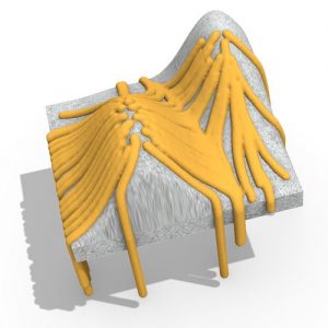
FIGURE 3. Constructed Algorithm in Grasshopper
There are some basic steps in the manufacturing pipeline of 3D printers. It starts from the design stage and ends with the fabrication of the designed geometry. In between these stages, slicing algorithms are utilized to obtain the layers of the parts and then the toolpath trajectories are generated according to the fundamentals of the corresponding Additive Manufacturing (AM) approach.
The resulting paths are usually represented via G-codes and then executed on the hardware of the corresponding AM machinery. As opposed to this conventional pipeline, an integrated approach is utilized in this study to fabricate parts having inhomogeneous interior structures for better tensile loading capabilities.
Throughout this study, the strength of the artifacts under specified tensile loading is improved. The specimens are manufactured by an open-source FFF 3D printer (DeltaWasp 2040) utilizing PLA material. As described above, the method starts from the design stage and it is now only valid for 2.5D geometries which means that the geometries are drawn in 2D-plane and extruded through the vertical axis. For the design of the geometries, Rhinoceros3D is used as the CAD software.
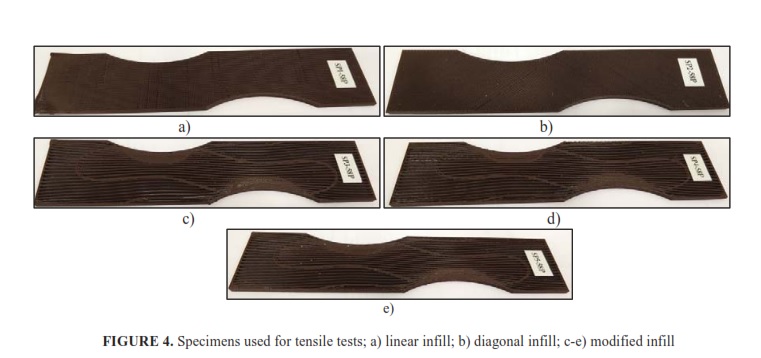
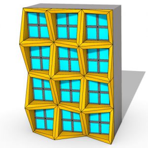
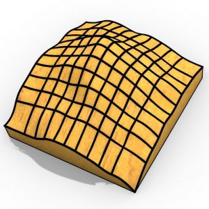
FIGURE 4. Specimens used for tensile tests; a) linear infill; b) diagonal infill; c-e) modified infill
A primitive and manual version of this approach was discussed in the earlier work of the authors [8]. For this automated version of the approach, a custom part having necks on both sides is designed and provided in Fig. 1. Its sizes are adjusted according to the building area of the 3D printer.
To prove the validity of the proposed methodology, tensile tests are performed on the 3D printed parts under the same specified loading employed on FEA. These tests are conducted on Instron 8802 Servohydraulic Fatigue Testing Machine which has 100 kN force capacity and located in the Material and Processing Laboratory (M&P) of the Turkish Aerospace Industries (TAI). The aim of the tests is to determine the loading capacity and the strength of the artifacts.
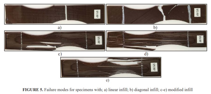
FIGURE 5. Failure modes for specimens with; a) linear infill; b) diagonal infill; c-e) modified infill
During this study, a lot of tensile tests are performed for different geometries such as ASTM-D638 type 1, rectangular geometries, rectangular geometries with holes, etc. Geometries are randomly chosen to prove the applicability of the method.
The geometry named rectangular with the neck is considered within the scope of this paper. This geometry is modeled in Rhinoceros3D and defined in Grasshopper3D to be used by the developed paradigm. After processing the method on this geometry, a G-code to print is generated. In addition to three test parts with modified interior structure, two more test parts having linear and diagonal infill patterns are printed utilizing the software of the 3D printer. All the parts are set to have an infill percentage of 58, but the actual percentages are not equal to 58% due to the little problems on the 3D printer.


Comments