
Concrete Shells
Seamless rigid connections of thin concrete shells – a novel stop-end construction technique for prefab elements
Philipp EISENBACH*, Manfred GROHMANNa, Moritz RUMPFb, Stephan HAUSERc
*PhD Candidate School of Architecture, University Kassel; Bollinger + Grohmann Ingenieure
a Professor – School of Architecture, University of Kassel; Bollinger + Grohmann Ingenieure
b PhD Candidate – School of Architecture, University of Kassel
c Dr.-Ing. – Director DUCON Europe GmbH & Co. KG
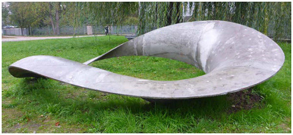
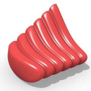
Figure 1: Concrete bench after construction.
Lightweight concrete structures and structurally optimized systems are in focus of several research interests – not only due to architectural motivations but also in order to use material in a resource conserving manner. One significant challenge within the fabrication of slender shells often occurs with the construction of load bearing joints.
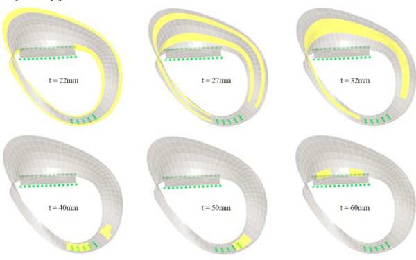
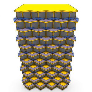
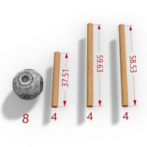
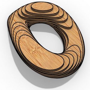
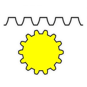
Figure 2: Concrete shell thicknesses.
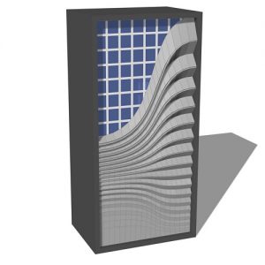
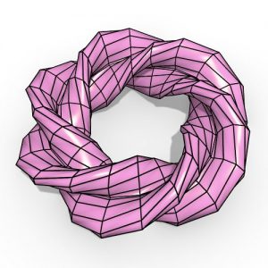
On the campus of University Kassel one can find an innovative, form active, ultrathin concrete shell structure designed as a Möbius strip. Due to the prefabrication in a laboratory as well as the absence of a crane it was mandatory to partition the object and to assemble elements on site.
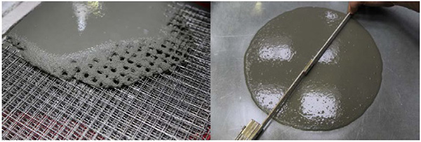
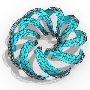
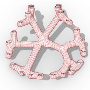
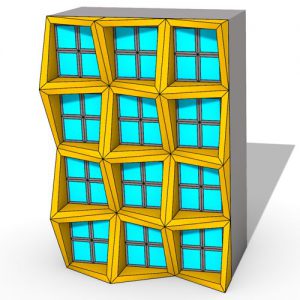
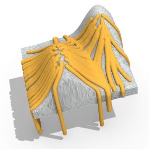
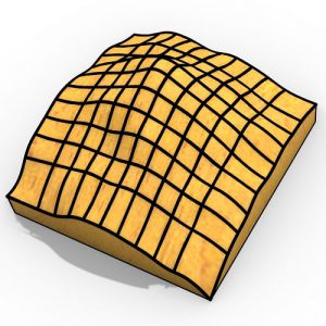
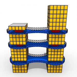
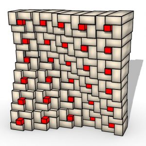
Figure 3, 4: The mesh wire reinforcement is a multiple layer system over the entire cross section of the shell. That leads to high requirements to the fluidity and hence the mixing process of the concrete controlled with the slump before pouring into the formwork.
The chosen material is DUCON®, which stands for DUctile CONcrete. It is a composite material of a high-performance concrete and a micro reinforcement of multiple layers of interconnected steel wire meshes stapled over the entire cross section.
The structural concept envisaged a fully rigid system so a novel stop-end construction technique for the mesh reinforcement was developed. To guarantee the rigidity of the connected joints, the reinforcement layers need to overlap and thus the requirement of casting stop-ends for the mesh reinforcement occurs.
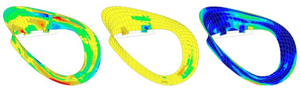
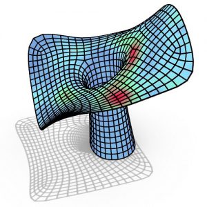
Figure 5, 6, 7: From left to right: Axial stress distribution diagram (red:=tension, blue:=compression); in-plate bending moments (yellow:~zero); principal stress distribution.
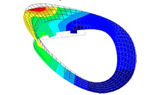
Figure 8: First failure eigenmode from buckling analysis.
The solution is the preparation of the joint with a water soluble mortar, placed at the connection boundaries of the prefab shell element that can be washed off after the curing process of the concrete. The joint itself is then cast individually on site.
An extensive investigation of the load bearing capacity of the join system has been executed with four-point bending tests. The appraisal of the force-deflection diagrams as well as the fracture appearances and distribution of cracks validates the developed connection system as feasible.
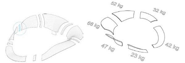
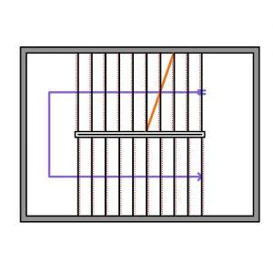
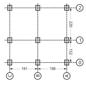
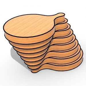
Figure 9, 10: The location of the joints is determined geometrically to fit within in layout and the selfweight was limited to 70kg to be able to carry by hand.
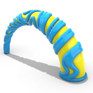
The Möbius strip was discovered by the mathematician August Ferdinand Möbius in 1858 and describes a surface with only one edge. Taking a strip of paper, twisting one end 180° and sticking the ends together gives a Möbius strip. Even cutting the entire strip at the half doesn´t lead to two strips – it remains one. Möbius strips don’t have in- and outsides. If one starts to paint one apparent side, the whole strip will be colored at the end.
The envisaged concept of the concrete bench reflects the omnipresence of science at a university. The bench like sculpture has areas to sit on, to lie on or to lean against. Those areas are defined through the different heights of the bench. The sculpture opens up towards the canteen to invite visitors to take a rest on.
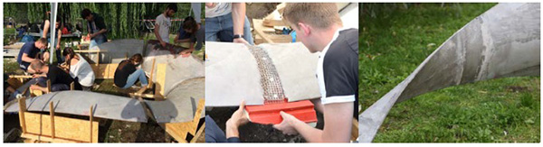
Figure 11, 12, 13: From left to right: The individual pieces were aligned on site and the reinforcement was bent in final position. After that the formwork of the joint connection is installed and tightened and finally cast. After stripping the formwork a load bearing connection is achieved.
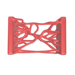
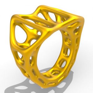
The geometry is parametric built with Grasshopper, a plugin for the 3d modelling software RhinoCeros3D. First and foremost the shape of the bench is driven by the design and functional aspects in order to achieve a convenient bench furniture. Having the initial geometry satisfying all functional boundary conditions the shape has been adapted with an optimization process performed with Karamba, Preisinger itself a plugin of Grasshopper.
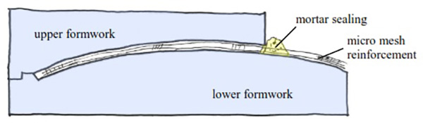
Figure 14: The concept of tightening the milled formwork envisages the usage of a water solulable water that can be washed of after hardening of the concrete element
Due to the slenderness of the concrete shell a buckling investigation is mandatory since it might be the governing failure design criteria. The areas of interest are those with compressive membrane forces at the outer edges where the shell has the smallest thickness and the smallest curvature.
With a nonlinear analysis the governing buckling shapes investigated. An imperfection of the shape imposed dependent on the length of the compressed edge. The buckling capacity is controlled by checking principle stresses under the influence of 2nd order analysis before and after the modelling of the imperfections.
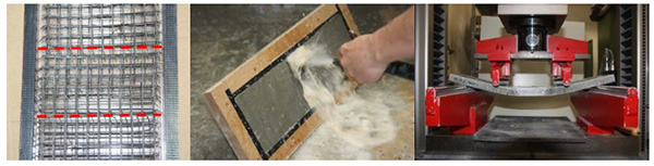
Figure 18, 19, 20: From left to right: Mirco mesh reinforcement in the joint area. This example shows the overlapping version, type B-FU; the mortar sealing is washed out before casting the joint; four point bending test setup. The sample illustrates the ductile behaviour of the micro mesh reinforced concrete.
There are many ongoing research efforts to minimize the thicknesses of building elements made of concrete. Many interests are focusing in the increase of the composite material components like ultrahigh performance concrete (UHPC). This may result in the fact that those composite sections can be produced under laboratory conditions only, which leads to the question how to assemble single items on site.
With this research project, which arose during the design process, the authors were faced with the question how to bring single pieces together without losing load bearing capacity. The finding of a new stop-end technique for double curved concrete sections armed with micro mesh reinforcement is applicable for any geometry at any scale and opens up a wide variety in the planning process of slender concrete shells for engineers and architects.


Comments