
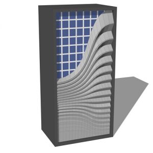
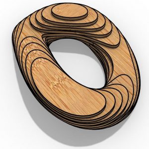
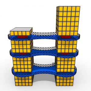
Parametric Bench
Have you ever wondered how to model a Parametric Bench in Rhino Grasshopper? In this tutorial, we are going to model a Simple Parametric Bench from scratch. You will learn how to deform a box and produce the sectioning in grasshopper. We will also cover how to Nest the sections for Fabrication.
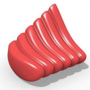
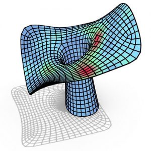
First step of this parametric bench tutorial is modeling the solid. In order to do so we are going to draw a box in rhino. If we want to be able to change the form of the box, we can select it and use “SolidptOn” Command.
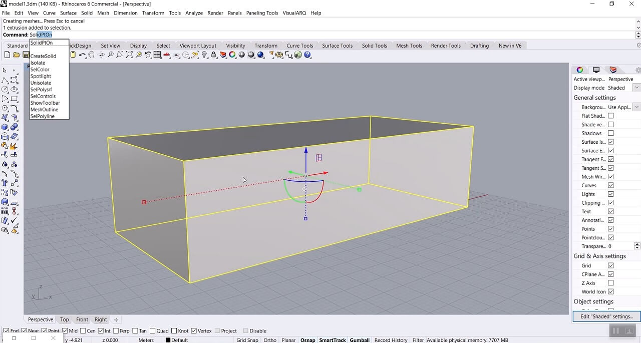
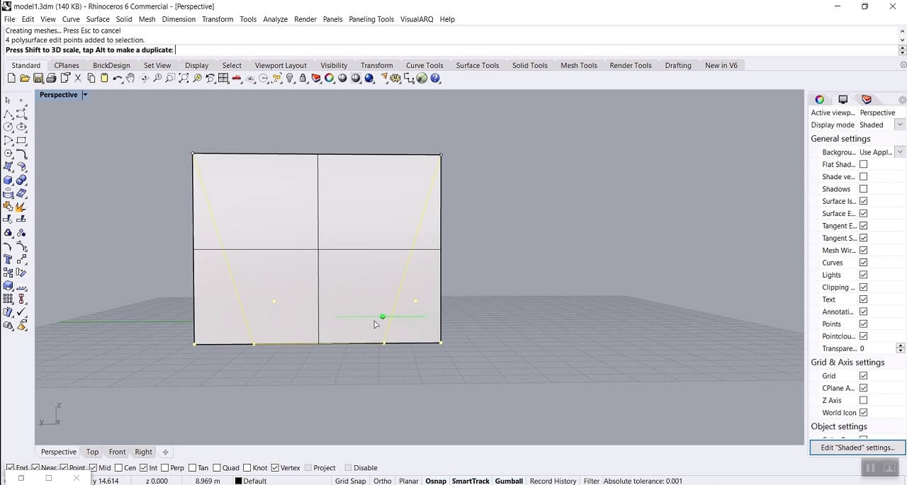
We can see that now we have points on the corners of our box, by selecting those points and moving them we can change the form of the box, for example change the height or length of it. Here we select bottom points and use gumball to scale them.
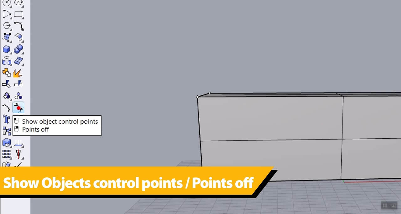
Now we can right click on “Show object control points / Points off” and turn off those control points.
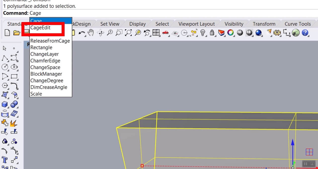
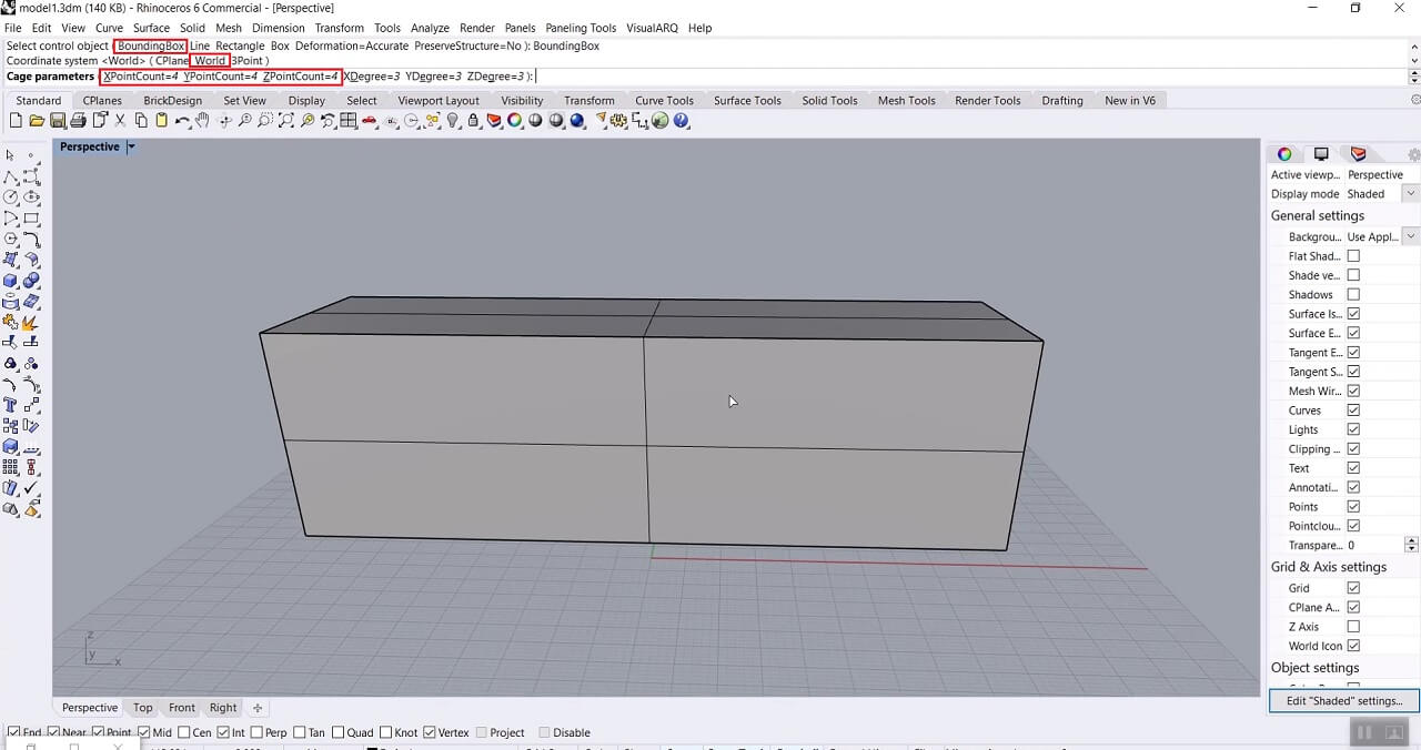
The next step is to use the “Cage Edit” tool. It will help us edit our form with a bounding box.
For the “Select control object” we choose “BoundingBox”, For the “Coordinate system” we choose “World” and then for the “Cage parameters” that defines the number of points in X, Y and Z direction, we choose 5 points in the X direction and 2 points in the Y and Z direction, to have a smooth deformation on the solid.
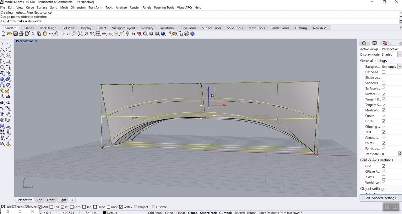
Finally for the “Region to edit” we choose Global. Now we have our control points and we can move them to change our form. Once we made those changes, we can turn the control points off and delete the bounding box.
To give this form some stability we can extrude both ends of the bench in the X-direction. In order to do so we can hold Ctrl and Shift and click on the surface we want to extrude. Then we can use gumball, click on that small circle in the X direction and give it the amount of extrusion we need.
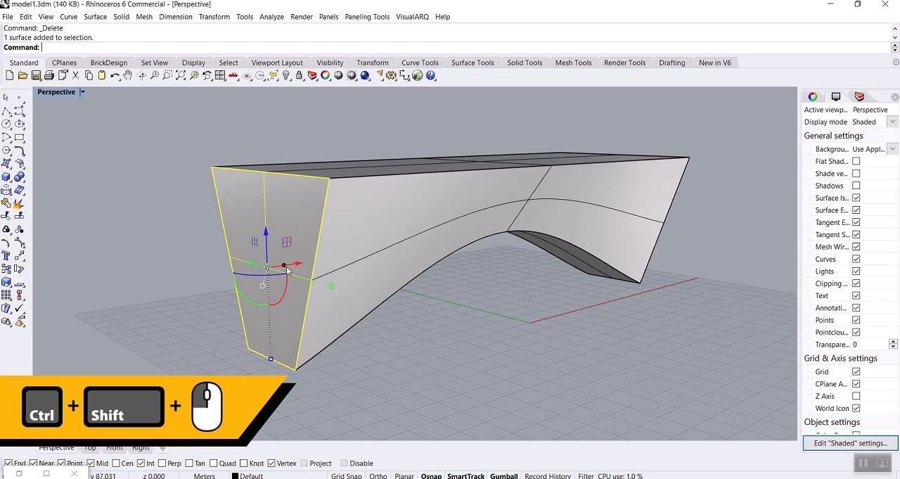
We can do it for both sides of the bench and now we have our form to use in grasshopper as a Brep.
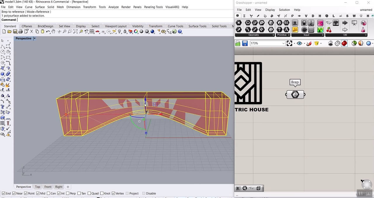
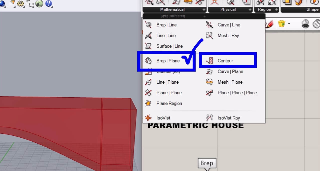
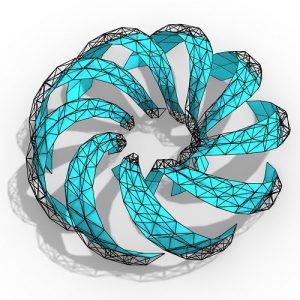
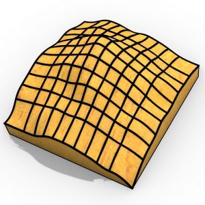
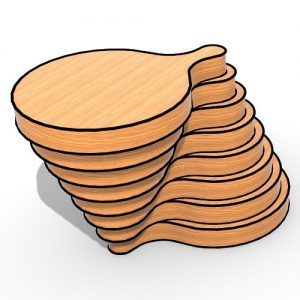
The next step is to produce a series of sections on this form. In the Intersection > Mathematical we have two options: “Contour” and “Brep|Plane”. Here we use Brep|Plane. The Contour component needs a starting point and a distance so if we don’t have the exact length of the bench and don’t set the distance according to the length, the last section doesn’t align with the other side of the bench, and we are going to have a bigger or smaller distance between our sections in the end.
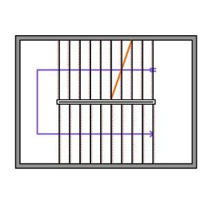
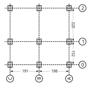
The Brep|Plane component needs section planes as input. To define those planes first we need to draw a line with the length of the bench in rhino. Use the curve component and import that line as a curve into grasshopper.
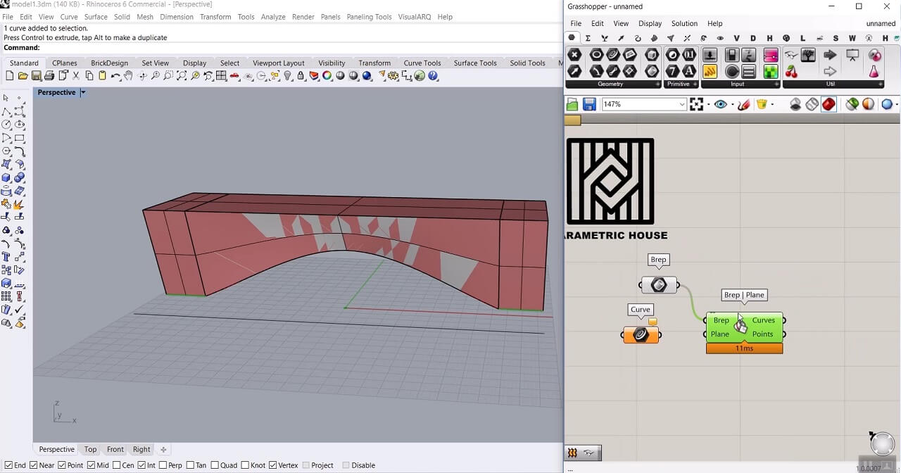
Now in the curve tab, we use the “Perp Frames” component which generates perpendicular frames on the given curve and uses those frames as section planes for Brep|Plane component.
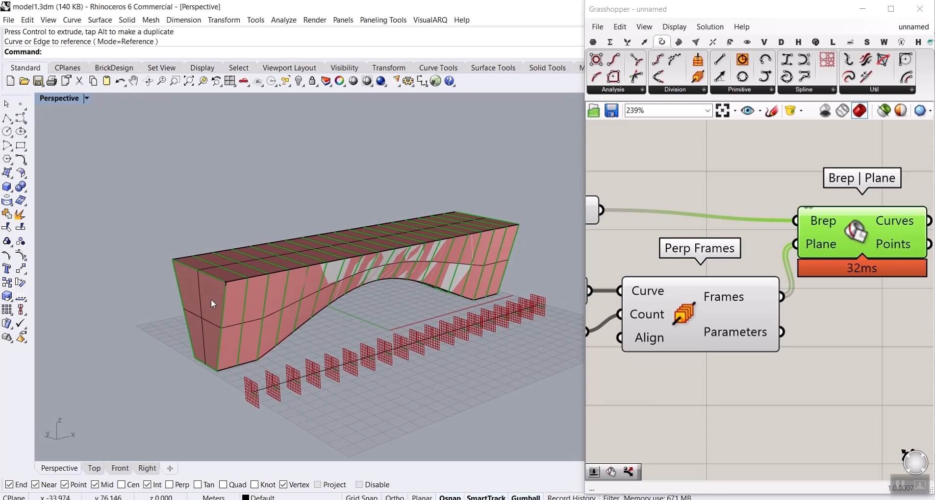
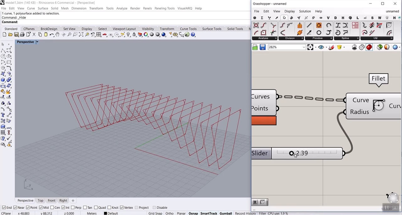
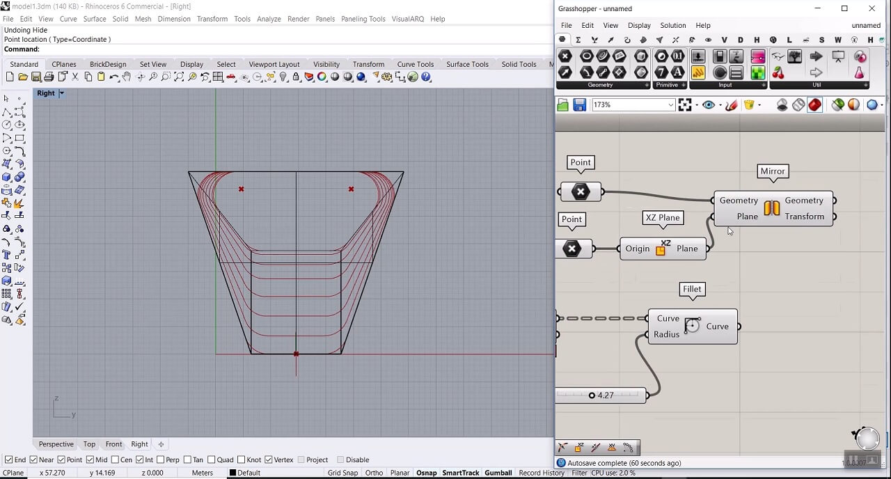
In order to make these sections smoother, we are going to use the Fillet component: Curve > Util. By increasing the number we give to the Radius input of the Fillet component, we can have smoother sections.
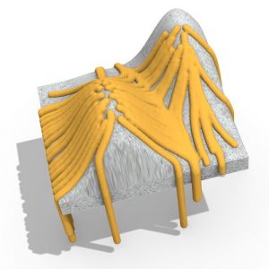
The next step is to define the pipes. Here using Point component we define two points. One for the center of one of the pipes and the other for the origin of a mirror plane. Then using Mirror component: Transform > Euclidean, we can have two symmetrical points for the center of the pipes.
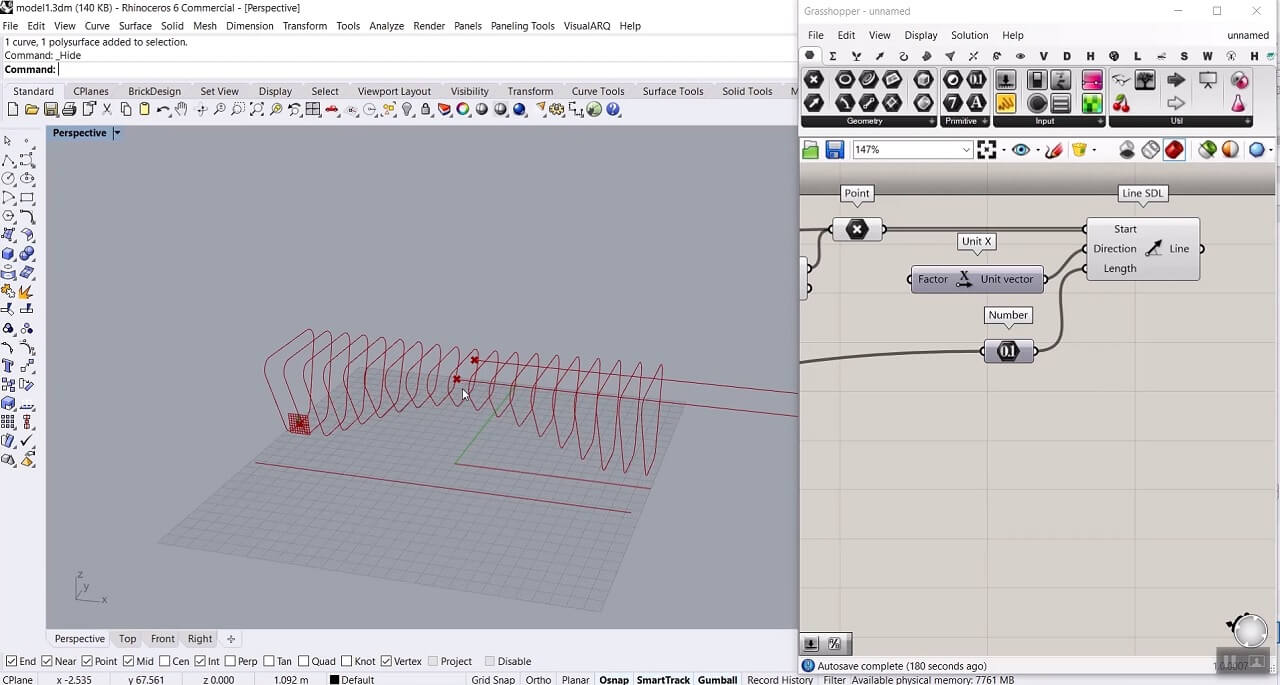
Now to define the axis of the pipes, we are going to use the Line SDL component: Curve > Primitive. The start point would be our two center points which we defined before, the direction would be X direction using the Unit X component, and for the length, we can use the length of the basic line we had for sectioning. To get the length of that curve we can simply give the curve as an input to the Number component: Params > Primitive and use it for the length of Line SDL.
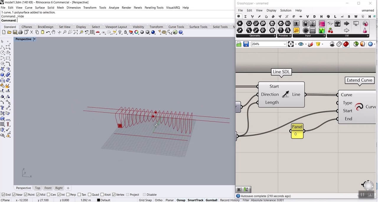
Now we need to extend those lines along the parametric bench with Extend Curve component: Curve > Util. Start input would be the length we gave to the Line SDL and End input would be 0.
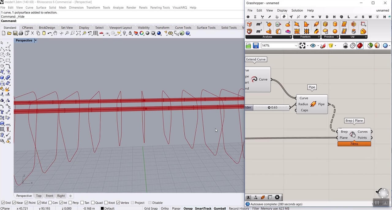
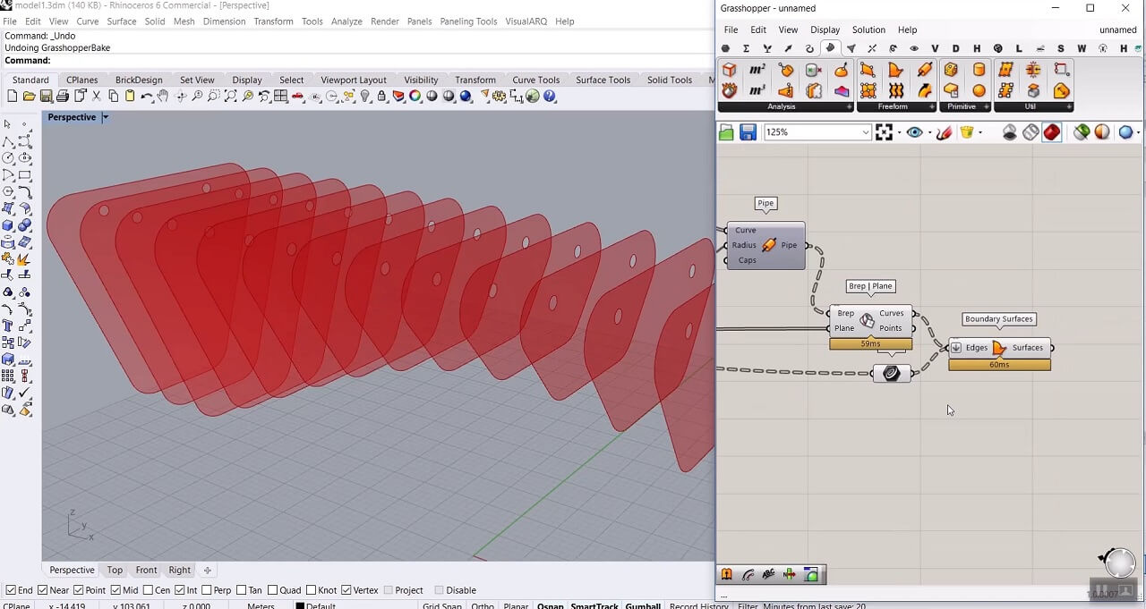
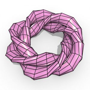
Then we can turn these lines into pipes using Pipe component: Surface > Freeform. We only need to give it a radius and have our pipes. Next, we should define the intersection between these pipes and our section planes using the same Brep|Plane component we had before, we can copy and paste the Brep |Plane component we have in the definition but this time give these pipes as Brep to it.
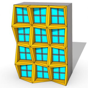
Now we have the boundary curves of the section planes and the intersection curves that we should turn them into a surface. In order to do so, we can use Boundary Surfaces component: Surface > Freeform and give those two sets of curves to that. For this component to work properly we need to flatten the input.
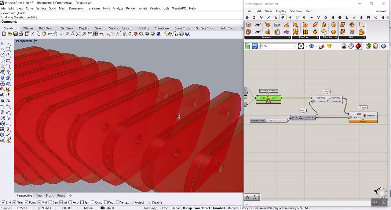
The next step is to extrude those surfaces in a way that our section planes would be in the middle of the extrusion. So first we move those section planes in the X-direction. The motion input would be our thickness divided by 2. We can give an arbitrary number in this case 2.2 to the factor input of the Unit X component and then right-click on the motion input of Move component and give it a x/2 expression. Now we should extrude the moved surface using Extrude component: Surface > Freeform. Here because the extrusion happens in the same direction that we moved those section planes, we need to right-click on the direction and give it a –x expression.
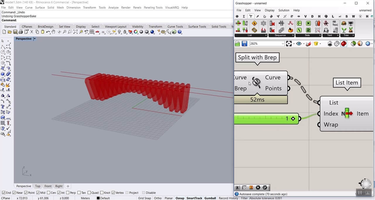
One other issue that we need to take care of is that the length of our pipes is bigger than the parametric bench itself so we have to split the pipes and only keep the middle part. We can use Split with Brep component: Intersect > Region and split the axis of the pipes we defined before (Extended Curve component) with the help of basic form of the parametric bench we imported from rhino as a brep. Then we need to use List Item component: Sets > List to choose the middle parts and turn them to pipes.
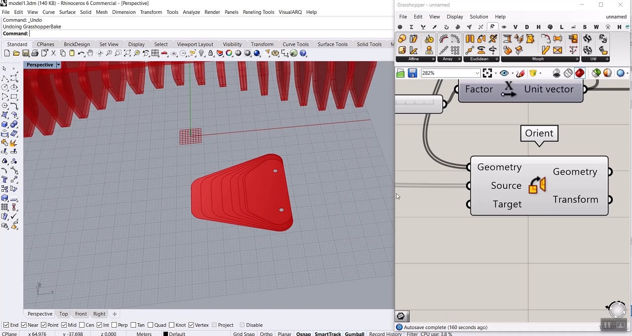
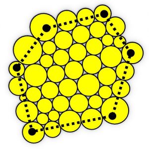
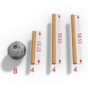
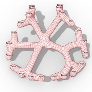
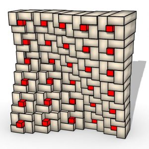
The last step to make this ready for fabrication is nesting. We can use the Orient component: Transform > Euclidean. This component is going to put a geometry from a source plane to a target plane. So we give the boundary surfaces to the geometry input, the source plane would be those perpendicular frames we defined before, and the target plane would be the XY plane.
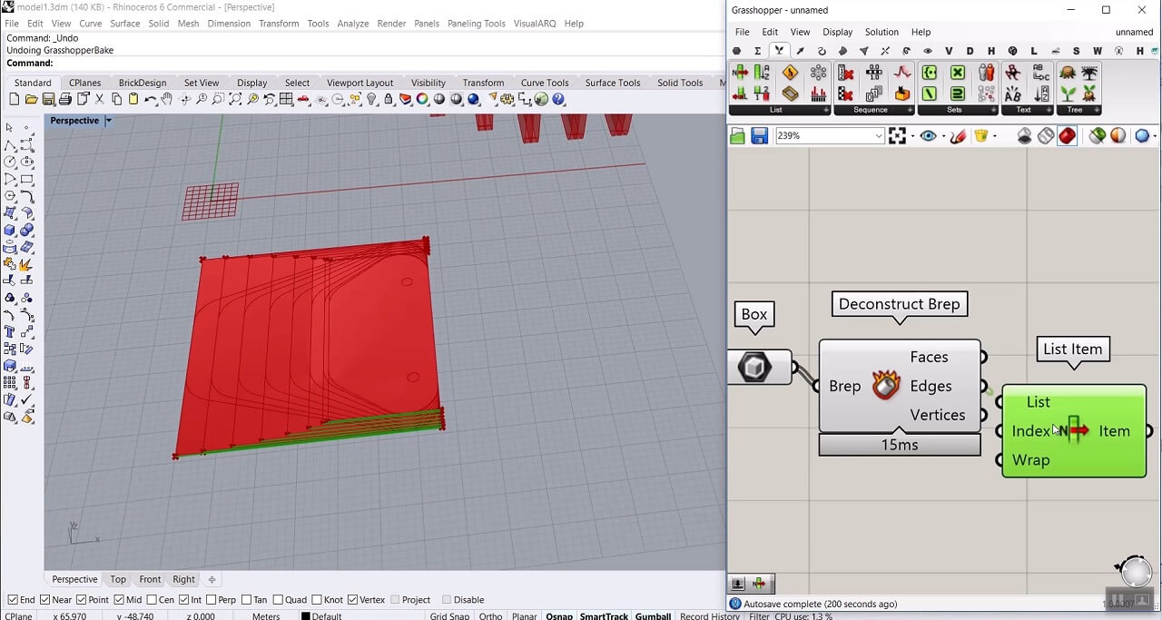
Now what we have to do is to give the geometry to a Box component, explode this box using Deconstruct Brep component, use List Item component to pick one of the edges.
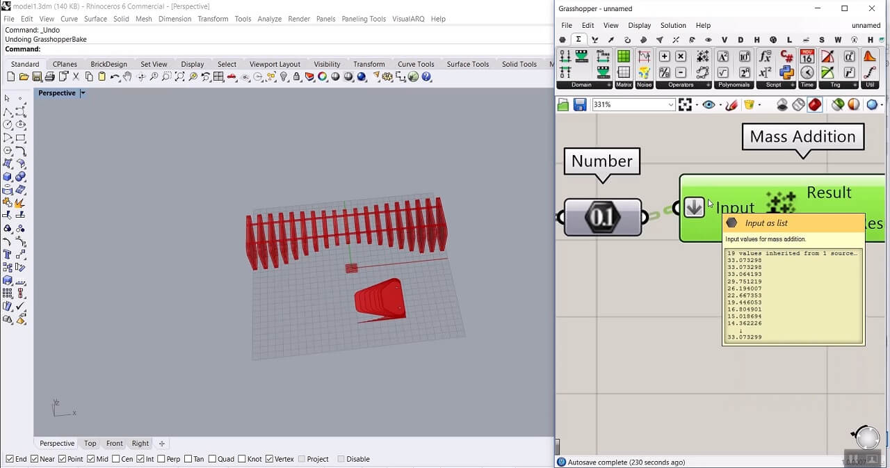
Then we use the Number component to have the length of these edges and also use the Mass Addition component: Math > Operators to add them up and flatten the input because we need those numbers to stack on each other for the partial results.
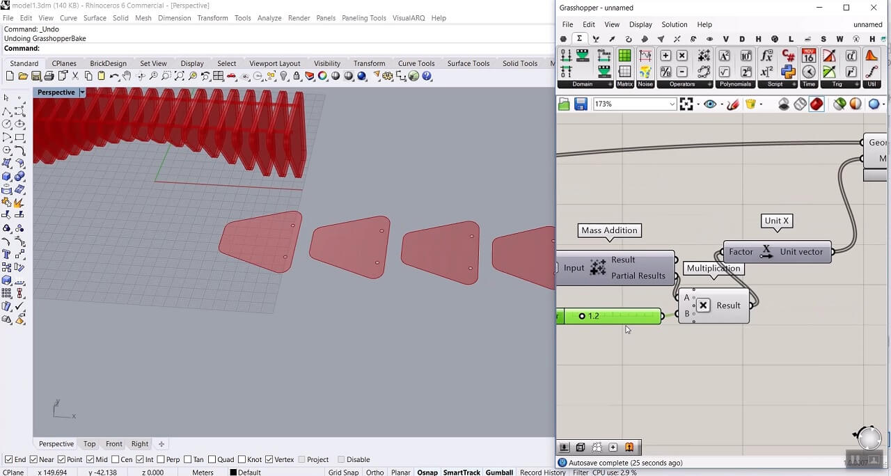
Now we can move those oriented curves in the X direction according to the partial results we get from the Mass Addition component multiplied by an arbitrary number.
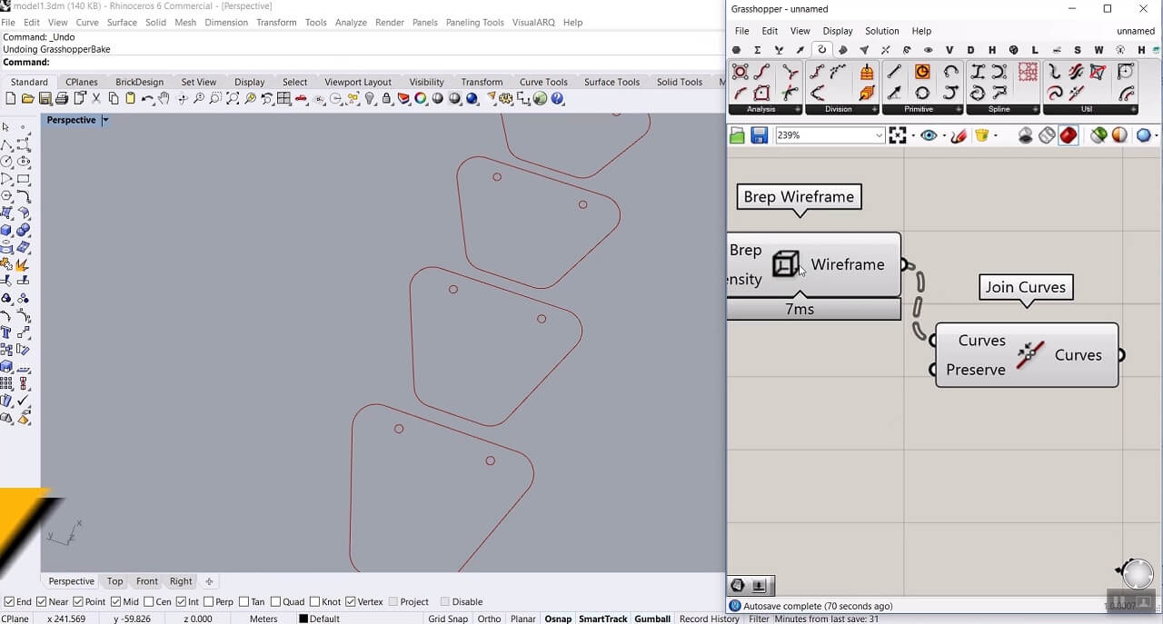
To have the curves ready for let’s say laser cutting we are going to use Brep Wireframe: Surface > Analysis, and also use Join Curves component: Curve > Util to have just 3 curves in each section.
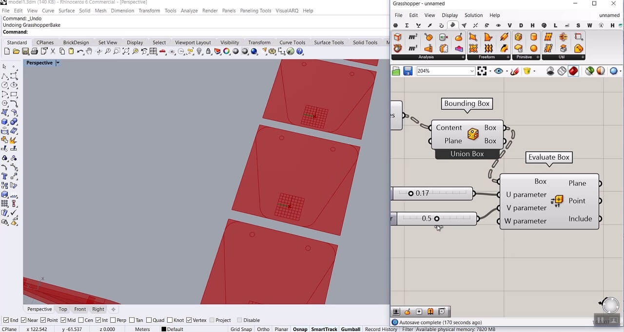
To put numbers on each section we have to put the curves we got into a Bounding Box component, right-click and choose Union Box, then use the Evaluate Box component: Surface > Analysis and give the Bounding Box to it. We can give the U and V Parameter inputs a number from 0 to 1 to change the location of the numbers.
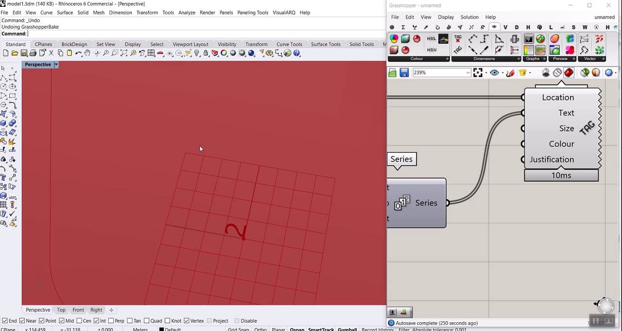
Finally, to put numbers in those locations, we can use Text Tag 3D component: Display > Dimensions. Give the flattened plane output of Evaluate box to the Location, define a series starting from 0, with 1 as step size and the number of the sections as the number of values in the series, and give this series to text input. Now we have our numbers, we can rotate them, also change the justification and size.


Comments
Felsager
This is top quality material for architects, engineers and furniture designers.