
Robotic Origami Worms
Multiphysics Simulation of Magnetically Actuated
Robotic Origami Worms
Ruphan Swaminathan, Catherine Jiayi Cai, Sishen Yuan, and Hongliang Ren, Senior Member, IEEE
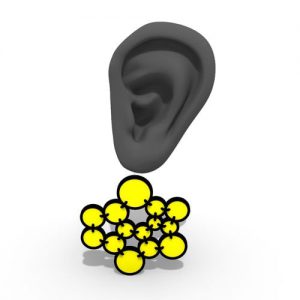
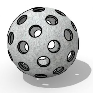
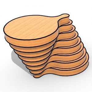
Fig. 2. Magnetic field around the two bar magnet models designed as an aggregation of magnetic dipoles. (a) Dipole density = 1 per cm3, (b) Dipole density = 64 per cm3.
Multiphysics simulation of magnetically actuated origami robots promises a range of applications such as synthetic data generation, design parameter optimization, predicting the robot’s performance, and implementing various control algorithms, but it has rarely been explored. This letter presents a realistic multiphysics simulation of magnetically actuated origami robots with a focus on real-time interactions between the origami and magnets.
Due to the interaction between multiple magnets, the complex motion dynamics of a worm-like robot are generated and analyzed. We further show the possibility of accurately simulating origami structures made of different materials and permanent magnets of different shapes, sizes, and magnetic strength.
The simulation’s unknown parameters are determined by conducting similar practical and simulated experiments and comparing their characteristics. Further, we show the close resemblance between the real and simulated behavior of the origami robot.
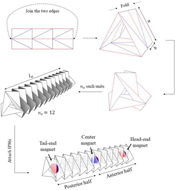
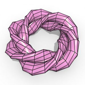
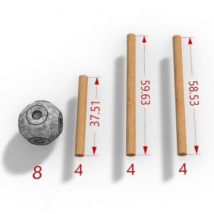
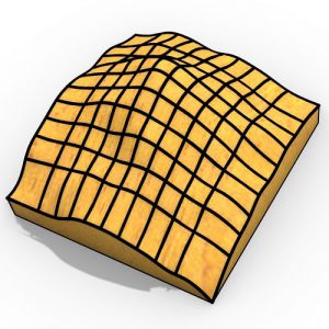
Fig. 3. Construction of the worm origami robot. The red lines denote the valley folds, and the blue lines denote the mountain folds. The parameters a, b, and n are chosen according to the simulation’s requirements.
Origami is an art of letter folding and was initially introduced as a form of art. The underlying principles of origami have been applied to suit the needs of various engineering applications, ranging from packaging in manufacturing industries to foldable solar panels in satellites.
In particular, origami concepts have a vast potential in robotics as sophisticated 3D mechanisms can be developed from 2D sheets, giving rise to origami-inspired robots with versatile functionalities. Due to their compatibility with established 2D fabrication techniques, the design and fabrication of robotic structures can have the potential to be inexpensive, fast, and precise.
By incorporating internal permanent magnets (IPMs) into the origami robot structure, the robot can be remotely magnetically actuated via an external permanent magnetic field. As magnetic actuation does not require an onboard power source, the origami robot can be compact and lightweight. These factors make them suitable for biomedical applications, such as drug injection and minimally invasive surgeries.
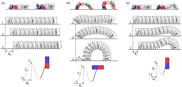
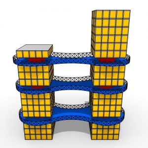
Fig. 4. Generation of different translational motions using by varying the EPM’s orientation and trajectory in the Grasshopper3D. The experimental versions are shown on top of the corresponding origami motions. (a) Peristaltic motion, (b) Omega motion, (c) Inchworm motion.
The multiphysics simulation of origami worm robots under consideration involves solving multiple goals, such as the interactions between the IPMs and EPM, origami geometry, kinematics, dynamics, and each crease’s folding in the presence of multiple constraints simultaneously. This research problem has rarely been explored as a whole in a single simulation setup.
To address this gap in this letter, we present a multiphysics simulation of the origami worm robot fabricated in our previous work. All the simulations performed are done using Grasshopper 3D, a visual programming environment in Rhinoceros 3D. Kangaroo, a Grasshopper 3D plug-in, is used to set practical constraints and iteratively simulate the system.
Kangaroo simulations are nonlinear, making them ideal for worm-like origami simulations, which tend to have large deformations from the initial state. The solver of the first version of Kangaroo was implemented using a variational form of the implicit Euler method. The current version uses projective constraint-based solving, similar to Shape-Up, a general-purpose simulation tool.
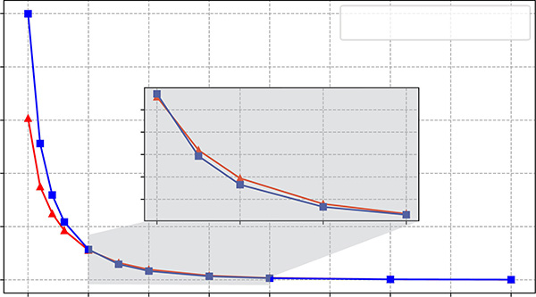
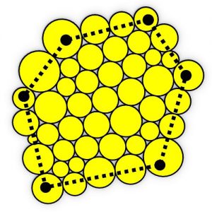
Fig. 5. The attractive force between two magnets (unlike poles facing each other) in the Grasshopper3D environment and the experimental setup. The close resemblance between simulated and real behavior in the origami’s operating range is shown as a magnified view in the inset, where the distance between the magnets is at least 5 mm.
A similar process of origami modeling has been done for the Miura pattern, and the authors show the feasibility of the algorithms compiled in Grasshopper 3D. Apart from predicting robotic origami structure’s performance, a realistic simulation has other advantages: exploring design parameter space exhaustively and generating huge datasets for training artificial neural networks, typically costly for realistic robotic experiments.
Since a magnetically actuated origami robot is an open-loop control system, it is necessary to obtain closed-loop control feedback. One way to obtain this in real-time is by using a camera to capture origami structure, which can be used as an input to a deep learning neural network to estimate the origami’s configuration. In such cases, obtaining real datasets becomes an exhausting task due to the amount of data and labeling required.
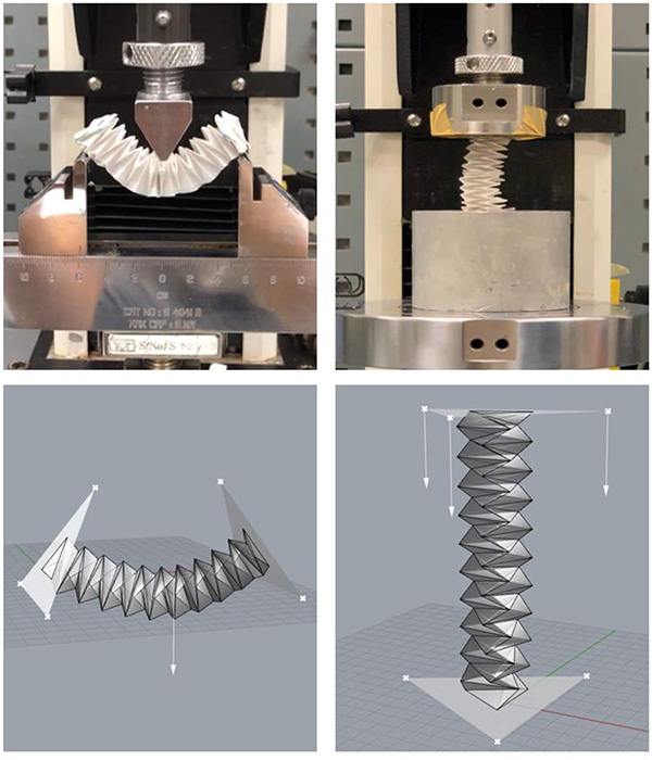
Fig. 6. Test environment to perform the compression and 3-point flexure test in the experimental (top) environment. The same test is employed on the simulated origami structure (bottom) to determine the Hinge component’s strength parameter.
Deep learning models can be trained on a simulated dataset and transferred to work on real data using techniques such as domain adaptation and randomization with minimal manual dataset collection. This letter contributes (1) Realistic multiphysics simulations of magnetically actuated origami worm robots in Grasshopper3D; (2) Real-time simulation and interaction with the origami and magnets; (3) Facilitate implicit setting of the type of material of the origami; (4) Generation and analysis of complex robot mechanics, kinematics and dynamics.
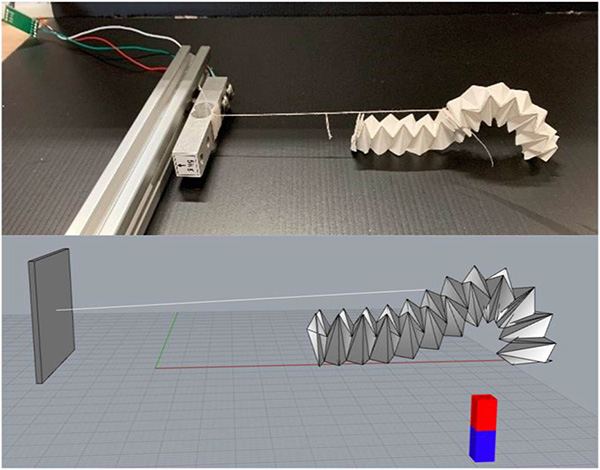
Fig. 9. Measuring the force exerted by origami (inchworm motion) in the experimental (top) and simulation environment (bottom).
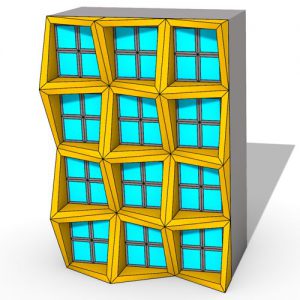
In general, origami robot design and simulations assume rigid facets due to their negligible bending and reduced computational complexity. Thus, even though the individual triangular facets are rigid, the mesh is overall a non-rigid body due to the foldability at the creases. Similar to the mesh facets being modeled as rigid panels to avoid bending, all the mesh edges, which include the creases, are modeled as rigid beams to avoid stretching of the letter. The creases are also modeled as revolute joints that connect two triangular facets.
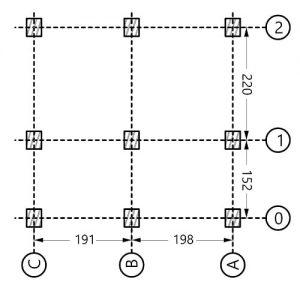
The origami is divided into two equal sections – the anterior and the posterior half, to attach the magnets in the origami for suitable actuation. The IPMs are embedded in the three junction points, the tail end, the center, and the head end.
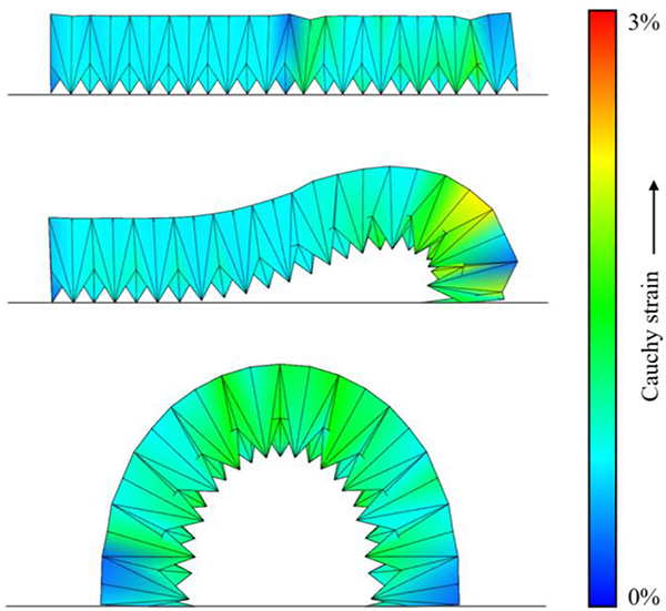
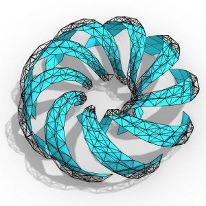
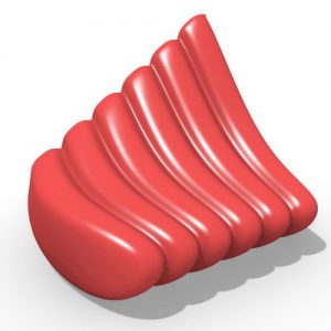
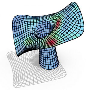
Fig. 12. Cauchy strain experienced by the origami during different motions is visualized by using a color gradient from blue (no strain) to red (maximum strain).
The nature of the creases varies based on the type of material used to make the origami robot. The folding angle of the origami, which depends on the crease stiffness, can be determined by physically measuring the origami robot’s length using eq.
One of the origami robot’s vital functions is to move objects by exerting a force on them. For example, an origami robot used in minimally invasive surgeries needs to push/pull polyps and tissues. Hence it is necessary to predict the characteristics of the dynamic force exerted by the origami during various motions.


Comments