
Spatial Augmented Reality
Rough Carving of 3D Models with Spatial Augmented Reality
Ammar Hattab, Gabriel Taubin
Brown University Providence, RI
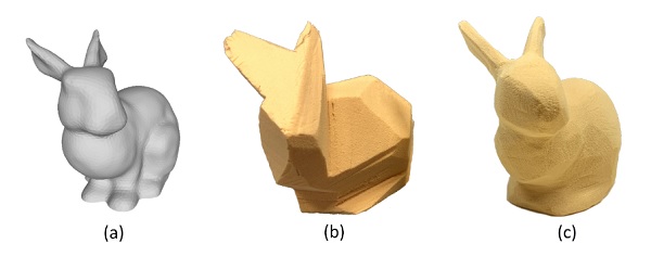
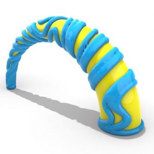
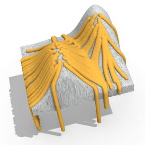
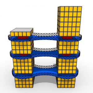
Figure 1: We assist users in roughly cutting a 3D model. (a) Given a target 3D model, we generate an optimized sequence of cutting steps and use a projector to project them to a block of material to guide the user in performing them. (b) Rough carving result. (c) Fine carving result.
Carving is a subtractive process where we get the shape by removing materials. While most people can get roughly the right intended shape, it is usually challenging not to over-cut the model.
We propose a method that helps an unskilled user to carve a rough physical replica of a 3D model using the minimum number of cuts while only using manual cutting tools.
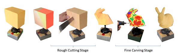
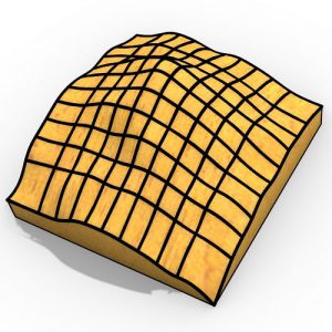
Figure 2: Two stages of carving: rough cutting and fine carving.
The method starts by analyzing the input 3D model and generates the minimum set of cutting steps that remove most of the material.
Then using a projector, we project the instructions sequentially onto a block of material to guide the user in performing them.
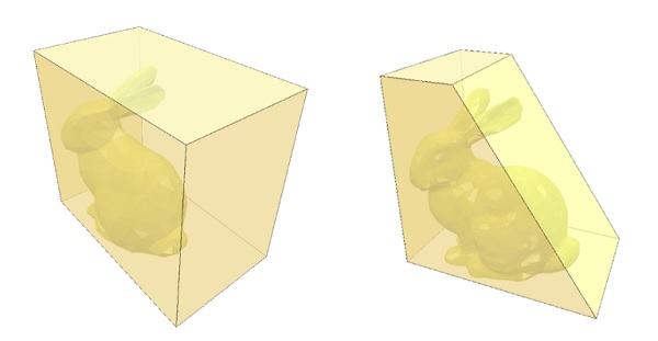
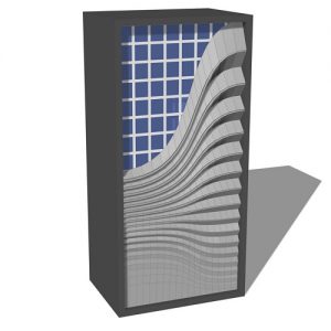
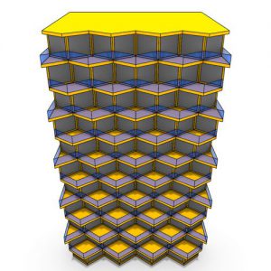
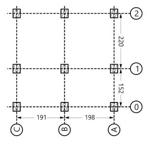
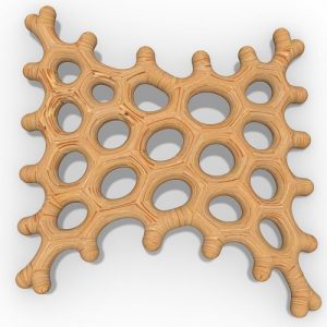
Figure 3: Left: The bunny 3d model takes only 17.5% of the total volume of the shown block, the rest will become dust. Right: A single cut removes 40% of the total volume of the block of material.
We use the projector-camera setup to 3D scan the object after cutting and automatically detect the changes to reflect them on the digital model.
We demonstrate a complete system to support this operation and show several examples of manually carved 3D models while using the system.
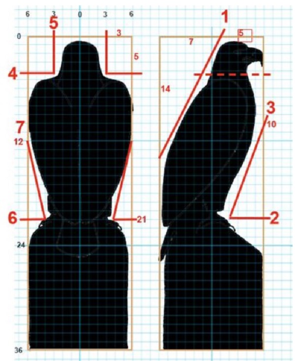
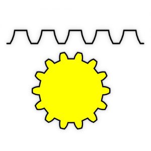
Figure 4: Chainsaw Carving guide for beginners. Two types of cuts shown; straight cuts like cut number 1, and stop cuts like cuts number 2 and 3. Image source: ChainsawCarve.ca.
A large number of people practice the manual carving craft. But for beginners, there are two challenges; the first is to get the right proportions of the carving in 3D, the second is not to over-cut the model.
Most people don’t have the skills to carve the intended shape from a mental image without over-cutting parts of it. In this paper, we introduce a method to help novice users carve 3D models by using a projector to project guidance colors onto the material.
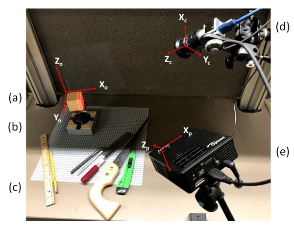
Figure 5: A projector-camera setup: (a) Block of material. (b) The carving stage that could be rotated by 90 degrees. (c) Cutting tools. (d) Camera. (e) Projector
Our approach is similar to the previous methods like the “Shape Shift” [Skeels and Rehg 2007] or the “Sculpting by Numbers” [Rivers et al. 2012], but in this paper, we focused on the rough carving stage.
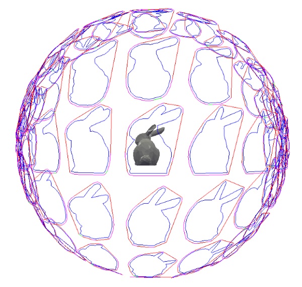
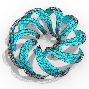
Figure 6: Our method starts by computing the silhouettes of the 3D model from a uniformly distributed set of directions. Then it computes the best cutting steps from the silhouettes.
Carving is usually done in stages. First, the rough stage where the user wants to remove most of the material quickly, without overcutting the model.
Then, the fine carving stage, where the user moves to a different tool to remove smaller and smaller amounts of material, while adding in the fine details of the model.
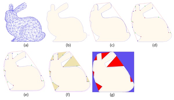
Figure 7: For each chosen direction: (a) Vertices projection. (b) Computed Silhouette. (c) Convex hull of the silhouette. (d) Extreme points that define the stop-cuts. (e) Offset the silhouette and the convex hull. (f) Concave regions (stop-cut). (g) Blue regions show material that can be removed by planar straight cuts. While the red regions show material that can be removed by stop-cuts.
For the rough stage we introduced a novel method to provide the user with cutting instructions to carve a rough physical replica of the model, while for the fine stage we followed the “Sculpting by Numbers” [Rivers et al. 2012] approach to project colors onto the evolving block of material as visual feedback to indicate to the user how far from the intended shape the current shape is.
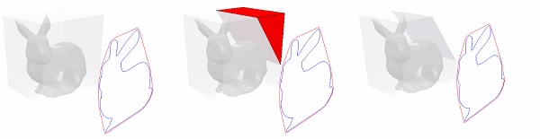
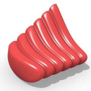
Figure 8: Planar cuts are generated from the convex hull of the silhouette. (a) Silhouette in a specific direction. (b) The red region represents the material to be removed by a planar cut. (c) The model after removing the material.
Some 3D models are considered rough in general and need minimal fine carvings. In other cases, for example during prototyping, all the designer wants is the rough shape of the model to feel it in his hands, or to see how it fits in the environment and make adjustments. Fabricating a low-fidelity approximate model has many applications, for this reason a large number of the previous papers focused on that. Automatic fabrication machines like 3D printers or CNC milling machines are too slow for this purpose.
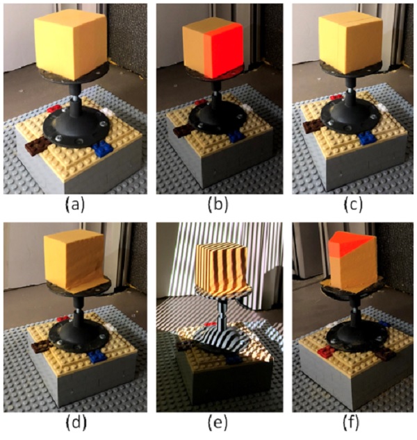
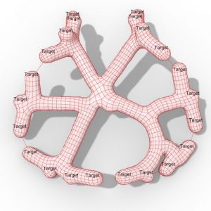
Figure 10: General process step. For a specific instruction, (a) First we find the best orientation, and we ask the user to orient the model to the specified orientation. (b) We project the instruction. (c) The user marks the places to be cut (optional). (d) The user performs the carving using hand tools. (e) We 3D scan the object, and compute the physical changes and apply them to the 3D model (f) Ready for the next instruction.
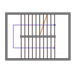
There are two ways people currently perform the rough carving stage. The first method is by marking the model silhouettes (from the front or side view) on the initial block, then cutting these silhouettes using some power saw machine, for example using a band-saw.
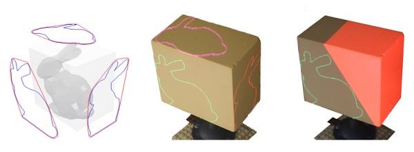
Figure 12: The same setup could be used for projecting Silhouettes.
The second method is to use a normal saw or a chainsaw to cut large chunks of the material quickly. The problem with the first method is that it only works well for models that align well with the three views (top, front, and side).
Also, once the silhouettes are cut on one side, it is harder to draw the silhouettes on the other sides. For more complex models, it is hard for most people to figure out the cutting steps in 3D.


Comments