Compact Reconfigurable Kirigami
Gary P. T. Choi1, Levi H. Dudte2, and L. Mahadevan2,3
1Department of Mathematics, Massachusetts Institute of Technology, Cambridge, Massachusetts 02139, USA
2School of Engineering and Applied Sciences, Harvard University, Cambridge, Massachusetts 02138, USA
3Departments of Physics, and Organismic and Evolutionary Biology, Harvard University, Cambridge, Massachusetts 02138, USA

FIG. 1. Reconfigurable kirigami design. (a) An enlargement of the unit cell of a quad kirigami tessellation illustrating the constraints on edge lengths and angles to be satisfied [Eqs. (1)–(4)]. The red dotted lines indicate the ordinary edge pairs corresponding to the same cuts, and the blue dotted lines indicate the dual edge pairs for getting the other contracted configuration. (b) The inverse design framework for reconfigurable kirigami. Starting with a given kirigami pattern and a prescribed target shape, we construct an initial guess in the deployed space and solve a constrained optimization problem to obtain a valid deployed configuration that satisfies both the ordinary contractibility constraints, and the new reconfigurability constraints, and matches the target shape. We then contract the deployed configuration in two ways, one by following the cut edge pairs and one by following the dual edge pairs to obtain two contracted states. The angles are colored based on the correspondence in the kirigami pattern.
Kirigami involves cutting a flat, thin sheet that allows it to morph from a closed, compact configuration into an open deployed structure via coordinated rotations of the internal tiles. By recognizing and generalizing the geometric constraints that enable this art form, we propose a design framework for compact reconfigurable kirigami patterns, which can morph from a closed and compact configuration into a deployed state conforming to any prescribed target shape, and subsequently be contracted into a different closed and compact configuration.

FIG. 2. The optimization process for producing a reconfigurable kirigami pattern. The two plots show the objective function [Eq. (7)] and the maximum constraint violation, which takes all constraints in Eqs. (1)–(6) into consideration. We use MATLAB’s fmincon optimization solver to iteratively update the coordinates of the nodes and change the pattern from the initial guess to an optimal configuration that matches the target shape and satisfies the reconfigurability conditions. As the pattern is reconfigurable, it admits two different closed and compact contracted states.
We further establish a condition for producing kirigami patterns and mechanisms which are reconfigurable and rigid deployable allowing us to connect the compact states via a zero-energy family of deployed states. All together, our inverse design framework lays out a path for the creation of shape-morphing material structures.

FIG. 3. Reconfigurable kirigami patterns. (a) For each example, the top row shows the two contracted states and the bottom row shows the deployed state which matches the prescribed target boundary shape [see Fig. 4(a) for more examples]. (b) Reconfigurable kirigami patterns produced by further enforcing a reflection symmetry constraint in the constrained optimization framework [see Fig. 4(b) for more examples]. (c) Energetics of the deployment and contraction of a reconfigurable kirigami pattern shows barriers near the two contracted states, but almost zero energy in between. This results in an unusual landscape, with monostable elastic minima at the ends and a mechanism-like zero-energy phase in between (see also the inset log-scale plot). The insets show the intermediate deployed states with each tile color coded by the total spring energy along all its edges and diagonals (denoted by e) (see Video S1 [23] and Appendix A for details).
Kirigami is the art of using cuts in a single sheet of paper that allow for changes in the shape of the sheet via coordinated rotations of the connected facets. In recent years, the art form has motivated the design of metamaterials wherein architected cuts on a flat, thin sheet of material can lead to unusual properties not found in most naturally occurring materials, such as a negative Poisson’s ratio.

FIG. 4. More examples of reconfigurable quad kirigami patterns with different target boundary shape obtained by our framework. (a) Patterns produced without enforcing any symmetry constraint. For each example, the two closed and compact contracted configurations and the deployed configuration matching the prescribed target shape are shown. Prescribing a symmetric target boundary shape does not necessarily yield a symmetric pattern. (b) With an additional left-right symmetry constraint enforced in the constrained optimization framework, the patterns produced will be symmetric.
There have been a vast number of studies on the geometry, topology, and mechanics of kirigami with applications to the design of nanocomposites, shape-morphing sheets, inflatable structures, soft robots, etc. Almost without exception, the deployed kirigami structures are open and periodic, and the property of admitting multiple closed and compact contracted states has been addressed only in a few well-known periodic regular kirigami patterns, and lead to states that are related to each other via global rotations.

FIG. 5. Conditions for multiple closed, compact contracted kirigami states can be mapped to linkage deployment. (a) The deployment of a generic four-bar linkage. The grey lines show the three deployment paths, two of which (the top and bottom rows) are degenerate. As for the nondegenerate one (the middle row), since the edges are not necessarily equal in length, it is not possible to achieve multiple closed and compact contracted states. (b) The deployment of a reconfigurable four-bar linkage. The grey lines show the three deployment paths, two of which (the top and bottom rows) are degenerate. As for the nondegenerate one (the middle row), note that the edges are equal in length and hence it is possible to achieve multiple closed and compact contracted states.
This raises a natural question: Is it possible to introduce cuts on a thin sheet of material in a way that yields a deployable and reconfigurable kirigami structure conforming to any prescribed shape and admitting multiple closed and compact contracted states?
Here we answer this question in the affirmative by building on our recent inverse design framework and identifying a set of geometric constraints to achieve both reconfigurability and a range of different energy landscapes associated with the deployment pathway. This allows us to design kirigami patterns that can undergo certain nontrivial shape changes under deployment to achieve a prescribed deployed or contracted shape, while also being reconfigurable and rigid deployable.

FIG. 6. An illustration of the constraints for reconfigurable, rigid-deployable kirigami design. Left: In kirigami patterns, each negative space (blue) formed by a generic deployed quad kirigami structure (not necessarily reconfigurable) is a four-bar linkage with two pairs of adjacent edges having the same length. Right: If the reconfigurability constraints are enforced, all links in the four-bar linkage have the same length. Such a linkage has three rigid deployments (shown by the dotted lines), one nontrivial path in which all angles between links are activated (the horizontal dotted lines with arrows in between the two dark green boxes in the pattern space and the reconfigured pattern space) and two degenerate paths connected by branch points at the ends of the first path (the vertical dotted lines in the green boxes in the pattern space and the reconfigured pattern space). The linkage can deploy rigidly from the branch point into either deployment paths, but cannot rigidly transform directly between points on the deployment paths while remaining embedded in two dimensions. If Eq. (9) is satisfied, the four-bar linkage in the pattern space will be as shown in the dark green box, and hence there is a rigid deployment path (as indicated by the green ticks) for morphing it from the pattern space to the deployed space and then to the reconfigured pattern space. However, if Eq. (9) is not satisfied, the four-bar linkage in the pattern space will be as shown in the pale green boxes, and so there is no rigid deployment path for reconfiguring it (as indicated by the red crosses).

FIG. 7. Reconfigurable, rigid-deployable kirigami patterns. (a) The deployment of a reconfigurable and rigid-deployable kirigami pattern at different states [see also Video S2 [23] and Fig. 8(a)]. The rigid-deployability constraints lead to a flat energy landscape, which indicates that the tiles do not deform throughout the process. Each black curve shows the trajectory of a tile center, with the black dot indicating its current position. The color of each tile indicates the orientation change (θ) with respect to the initial contracted state. (b) The deployment of two other reconfigurable and rigid-deployable kirigami patterns (see Fig. 9 for more examples). (c) Transforming the square to a circle [see also Video S3 [23] and Figs. 8(b) and 10 for more examples].
Since kirigami derives its properties via coordinated rotations of the individual cells, it is natural that the problem of kirigami design is close to the design of mechanisms, in which a set of moving parts are connected by kinematic joints to form a deployable structure.

FIG. 8. Physical models of reconfigurable, rigid-deployable kirigami patterns. (a) A physical model for the pattern in Fig. 7(a) cut from a clear acrylic sheet, with the tops/bottoms of pieces checkerboard colored red and black with permanent marker. (b) A physical model for the square-to-circle example in Fig. 7(c) cut from a multiply sheet. For each example, the green edges shown in the leftmost panel form the internal four-bar linkages and black edges complete the quad geometries. Quad interiors have been removed to reduce the weight of the models. Once the pieces have been laser cut, hinges are formed by applying small strips of light blue tape across pairs of vertical faces incident to the hinge vertex. The second left panel shows the perspective view of the assembled model. The right panel shows snapshots of the physical model at different states (see also Videos S4 and S5 [23]). All tiles in the physical model are rigid and undergo no deformation throughout the deployment, while the thickness of the tape joints has some minor effect at the two contracted states and so the model needs to be held still with a small external force at the end states
However, we note that while kinematic mechanism designs mainly focus on rigid-deployable structures formed by rigid bars, our inverse kirigami framework is applicable to both rigid and stretchable materials. Furthermore, by focusing on how the angles and edge lengths of the tiles in a given kirigami pattern can be changed to achieve the desired properties, we circumvent the role of designing structural topology for mechanism design.
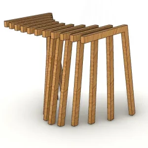
FIG. 9. More examples of reconfigurable, rigid-deployable kirigami patterns with different prescribed target shape. (a) An example of reconfigurable, rigid-deployable quad kirigami patterns at different resolutions. All four patterns can be deployed to approximate a prescribed circle. (b) Even with the additional rigid-deployability constraint, our framework is still capable of producing a large variety of patterns that exhibit highly nontrivial shape change throughout the deployment and contraction process and approximate different target deployed shape.
To crystallize our question in a minimal setting, we consider the quad kirigami patterns, a class of deployable structures obtained by introducing cuts to form quadrilateral tiles connected at hinges with a single global degree of freedom. To determine the size and orientation of the cuts that yield a deployed configuration approximating a prescribed target shape, it is more convenient to work in the deployed space and change the geometry of each tile.

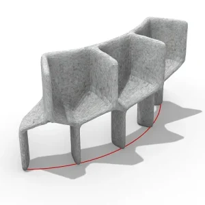
FIG. 10. More examples of reconfigurable, rigid-deployable kirigami patterns obtained by directly solving the optimization problem in the two contracted spaces. For each pattern, one of the contracted states is enforced to approximate a prescribed shape. (a) An example with the two contracted states and several intermediate deployed states. (b) More examples obtained by this approach, each exhibiting a significant shape change in between the two contracted states.

FIG. 11. Extending our framework for producing reconfigurable kagome kirigami patterns. (a) The reconfigurability constraints for the kagome pattern. The red and blue dotted lines indicate the ordinary and dual edge correspondences respectively, and the red and blue arcs indicate the ordinary and dual angle correspondences respectively. (b) The deployment and contraction of a reconfigurable kagome kirigami pattern.
In our recent work, we have shown that the key criteria for guaranteeing that the deformed deployed configuration yields a valid kirigami pattern, also known as the contractibility constraints, consist of the edge length constraints and the angle sum constraints.

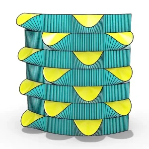
FIG. 12. Extending our framework for producing reconfigurable tubular structures. (a) Our framework can be extended for creating reconfigurable tubular structures which morph from one three-dimensional contracted configuration into another three-dimensional contracted configuration. Given a target three-dimensional (3D) shape, we first cut and unfold it onto the plane. We then solve the 2D constrained optimization problem with an additional periodic boundary constraint to produce a reconfigurable kirigami pattern for the planar shape. We can then map the design back to 3D to form a reconfigurable tubular structure. (b) Another reconfigurable tubular structure with a more nonuniform radial change throughout the deployment and contraction process. (c) A more complex reconfigurable tubular structure produced by assembling four copies of the pattern in (b).
As illustrated by the red dotted lines in Fig. 1(a), the edge length constraints enforce the constancy of the length of each pair of edges in the deployed space that correspond to the same edge in the pattern space: a = b, c = d, p = q, r = s.

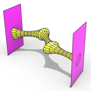
FIG. 13. An example of optimizing the boundary shape of the reconfigured contracted state. Note that only half of the boundary nodes at the reconfigured contracted state (see the blue nodes at the top boundary) can be enforced to lie on the target shape (the red closed curve) precisely. One reason is that the angle sum at the remaining half of the boundary nodes at the reconfigured contracted state (see the purple nodes at the top boundary) is constrained by the rigid-deployability constraints. Another reason is that those purple nodes come from the interior of the initial contracted state, which are constrained by the angle sum constraints and reconfigurable angle sum constraints therein. Enforcing them to lie on the target curve will introduce additional conditions on the relevant angles, making the problem overconstrained. Nevertheless, increasing the resolution of the kirigami pattern can help achieve a better approximation of the target shape even if only half of the boundary nodes in the reconfigured contracted state are controlled.

without imposing the rigid-deployability constraints [Eq. (9)]. (b) A reconfigurable kirigami pattern obtained by our proposed design framework with the rigid-deployability constraints included in the optimization process. In each example, the color of the angles in the first contracted state represents the value of log10[erd(α1, α2 )], and the color of the angles in the second contacted state represents the value of log10[erd(β1, β2 )], where α1, α2, β1, β2 are the angles described in Eq. (9)
While many prior works have studied the geometry, topology, and physics of kirigami patterns, the ability of achieving multiple closed and compact contracted configurations has not been understood. In this paper, we have taken the first step to explore the possibility of such compact reconfigurable design and show that one can achieve reconfigurability in addition to the shape constraints we introduced in our prior framework.

FIG. 15. Possibility of achieving other energy landscapes. (a) A 2×2 reconfigurable kirigami pattern that only satisfies half of the rigid-deployability constraints. More specifically, we have β1 + β2 = β3 + β4 = π in Eq. (9) while α1 + α2 = π. For this pattern, the energy landscape contains only one energy bump. (b) For a 3×2 reconfigurable kirigami pattern, note that the angles α1, α2 are related to the geometrical frustration in opening the negative space in one unit cell (highlighted by the blue dotted lines). After the deployment and contraction process, one can see that these angles are also related to the geometrical frustration in recontracting the negative space in another unit cell (highlighted by the green dotted lines). This shows that the constraints involving αi’s and the constraints involving βi’s in some neighboring cells are related, and hence one cannot eliminate one of the energy bumps by simply enforcing only half of Eq. (5).

FIG. 16. A physical paper model of the reconfigurable and rigid-deployable kirigami pattern in Fig. 7(a). (a) We consider each tile as a polyhedron with certain thickness and create a planar layout pattern with some extra small faces to give height to the folded pieces. (b) We can then obtain the paper layout patterns by laser cutting. The paper layout patterns are folded and glued to form the tiles (top), which are subsequently assembled using tape to form a deployable structure (bottom).
We have further shown that it is possible to enforce rigid-deployability in the inverse design framework via an additional set of geometric constraints. All together, our approach exploits the duality in kirigami patterns to create a class of reconfigurable kirigami patterns and planar mechanisms with multiple closed and compact configurations. Just as flat-foldability and rigid-foldability of origami opened the way for understanding and extending origami designs, perhaps their natural analogs in kirigami, viz. contractibility and rigid-deployability, that we have uncovered here might pave the way for a range of art-inspired mathematics, science, and engineering.