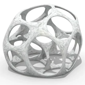
String Art Generator
String Art Generator by Yiran is a grasshopper plugin which generates a string art sequence based on an input image. You can
Frei Otto and the development of gridshells
The innovative architect, Frei Otto, developed the concept of gridshells which could be designed by a funicular modelling method and constructed from an equal mesh net of timber laths bent into the planned shape. In 1970
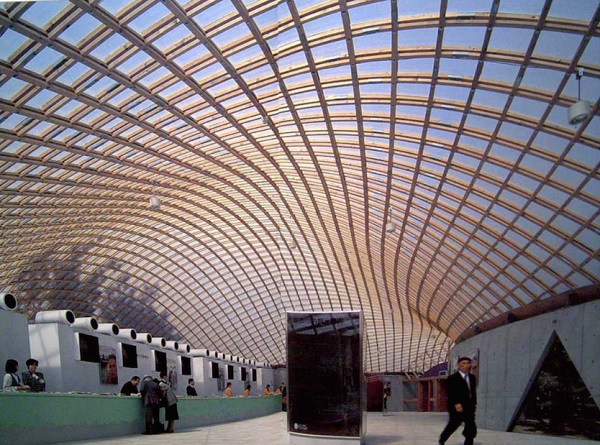
This technique was used to construct a 9000 m2 curved roof structure from 5 cm square timber laths. This paper summarises the design and engineering work that went into the construction of this remarkable building.
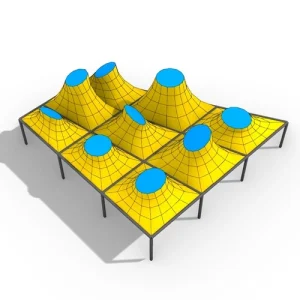
As well as tensile structures, in the late 1950s Otto became interested in light-weight shells which could be formed using the Hookean principle of inverting a hanging net (According to Lisa Jardine, Robert Hooke used this method to show Christopher Wren how the Dome of St Paul’s might work).
The formfinding method also suggests a construction method using an equal mesh square grid of timber laths or steel rods thin enough to be readily bent into shape.
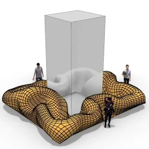
A square grid can be moulded to a doubly curved surface by the deformation of the grid squares into rhombi. Such a structure Otto described as a gridshell (gitterschale).
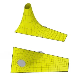
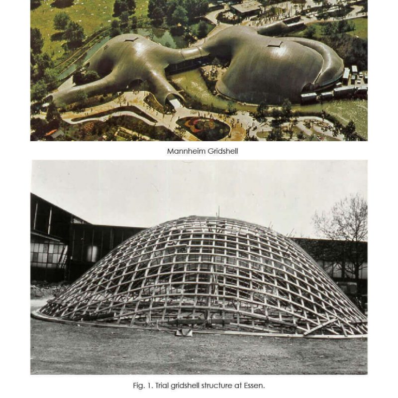
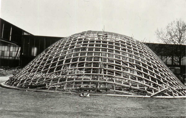
In 1962 he built, with some students at Berkeley, a trial structure of a dome standing on four points using steel rods. Later that same year he made a trial timber structure at Essen on a15 m × 15 m super-elliptical plan.
Two small auditoria were required within the Montreal Expo 67 tent and these were made using grid shell construction. The meshes were prefabricated in Germany and sent to Canada folded into bundles, where they were opened up and installed on site. The grids were clad with thin plywood sheets to form the enclosures.
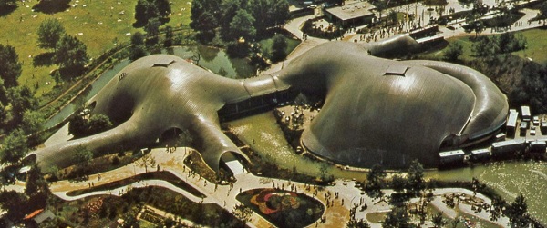
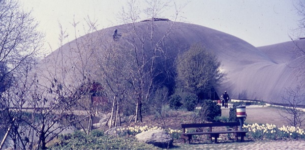
In January 1970 it was decided to hold the Bundesgartenschau 1975 in Mannheim. Carl Mutschler & Partners of Mannheim were selected as architects and Heinz H Eckebrecht of Frankfurt as landscape architect for the Herzogenriedpark.
The multipurpose hall building was to be the central feature arranged alongside a through route and with a restaurant on the other side.
A feature of the site in the flat plain of the Rhine was a large mound formed from demolition material left from the war and the landscape architect wanted a continuation of the hilly form by architectural means.
After some crazy ideas the architects remembered Otto’s grid shell trials and went to meet with him at Atelier Warmbronn.
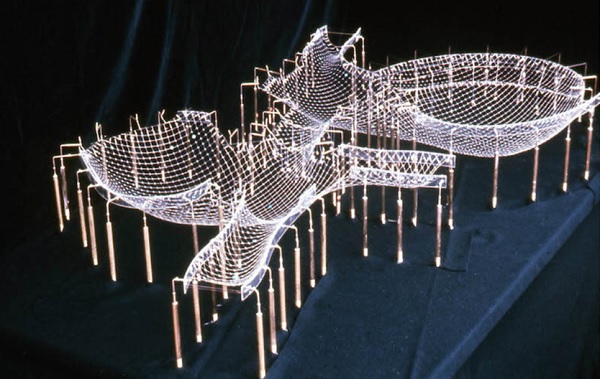
After some preliminary shapes were made with wire mesh the architects and the collaborators at the Atelier Warmbronn, particularly Evald Bubner, developed a 1:500 wire mesh model with two large dome structures and linking covered walkways.
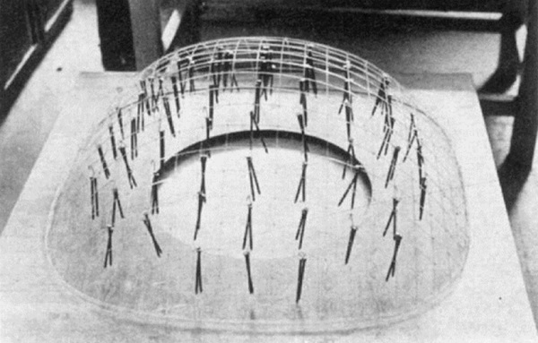
This was the sketch design. After this was agreed the architects finalised the boundary lines and the Atelier started work on the final hanging chain model that would define the geometry of the building.
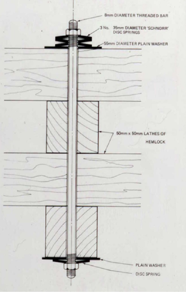
This was made with hooked links that connected with small circular rings that would be the nodes. The model scale was 1:100 and the chain grid dimension was 1.5 cm representing every third lath line on the real structure.
The ends of the link lines were connected to the boundary line with small springs that could be adjusted to achieve a reasonably uniform tension in the grid. Without such springs it is very difficult to get the forces reasonably well shared between the two directions of the grid.
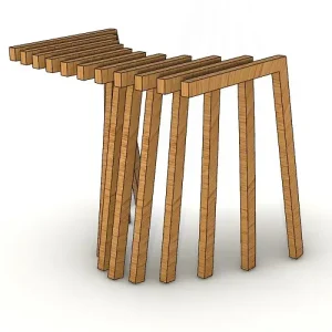
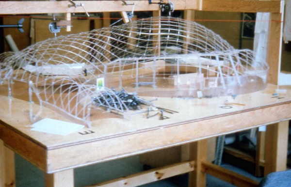
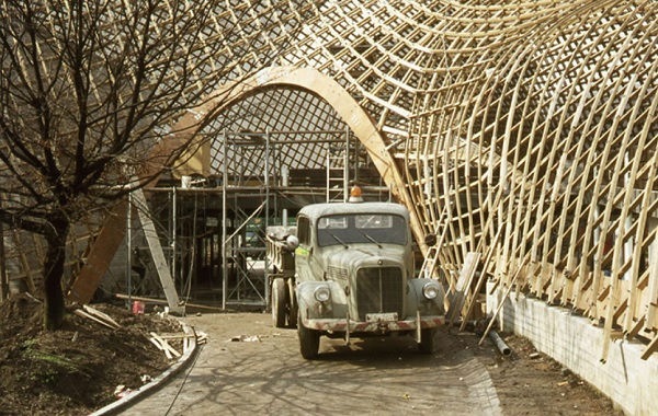
The installation started with the contractors laying out of the laths for the Multihalle shell on the ground without having a plan for lifting it.
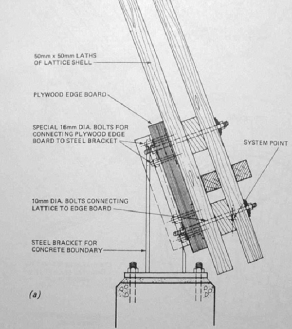
Their idea was to lift it with cranes but they realised that the shell would have to be supported in its correct position while all the nodes were set to the correct level, the node bolts tightened and the all boundaries fixed.
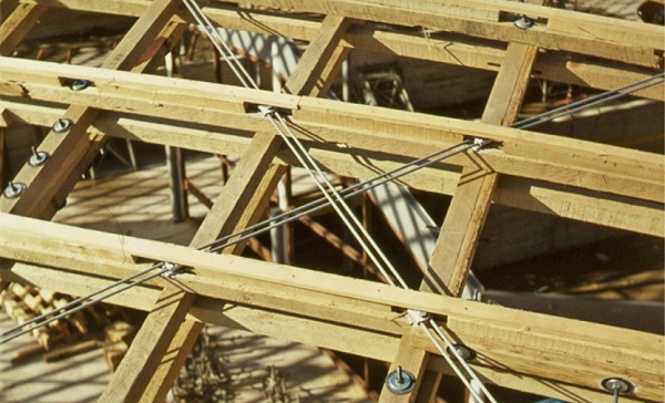
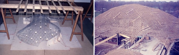
The additional shear block and diagonal ties would also have to be installed before the supports could be removed. To assist the contractors with understanding the problems involved the engineers made a model using wire mesh weighted so that the bending stiffness and self weight were modelled.
String Art Generator by Yiran is a grasshopper plugin which generates a string art sequence based on an input image. You can

This paper by Alessandro Liuti, Sofia Colabella, and Alberto Pugnale, presents the construction of Airshell, a small timber gridshell prototype erected by employing a pneumatic formwork.

In this paper by Gregory Charles Quinn, Chris J K Williams, and Christoph Gengnagel, a detailed comparison is carried out between established as well as novel erection methods for strained grid shells by means of FE simulations and a 3D-scanned scaled physical model in order to evaluate key performance criteria such as bending stresses during erection and the distance between shell nodes and their spatial target geometry.

In this paper by Frederic Tayeb, Olivier Baverel, Jean-François Caron, Lionel du Peloux, ductility aspects of a light-weight composite gridshell are developed.