String Art Generator
String Art Generator by Yiran is a grasshopper plugin which generates a string art sequence based on an input image. You can

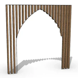
On funicular gridshells and Airy stress functions

2D graphic statics is a method originating in the 19 th century to analyse and design pin-jointed trusses using two reciprocal diagrams; the form diagram, which describes the structural geometry, and the force diagram, which describes the forces within the truss.

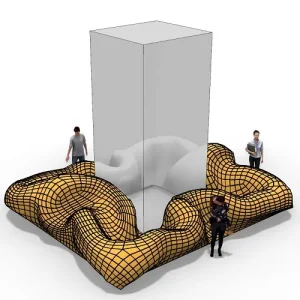
This paper investigates ‘2.5D’ graphic statics for gridshell design. This relies upon the form, force and slope diagrams. The force and slope diagrams combine, via a mixed area calculation, to give the funicular vertical load on a given node.

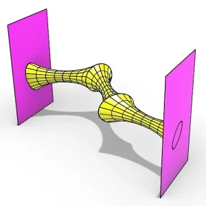
In the same way that the force diagram can be constructed from a discrete Airy stress function, so can the slope diagram be constructed from a plane-faced gridshell.
Both the plane-faced gridshell and Airy stress function are planar liftings of the form diagram. This new methodology allows the engineer to visually design the Airy stress function and gridshell simultaneously with the aim of producing gridshells which are both plane-faced and funicular with a given design load, such as a uniform projected loading.

Whereas in 2D graphic statics one can control the form and force diagram, here one can control the Airy stress function and gridshell geometry.
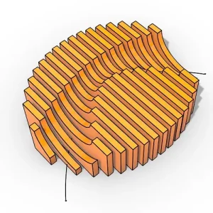
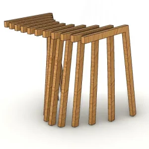
This paper also introduces the concept of mixed-Airy gridshells in which the Airy stress function and plane-faced gridshell are interchangeable for the same applied vertical load.

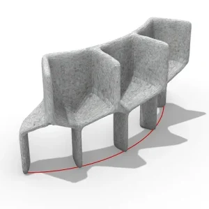
Self-Airy gridshells, where the Airy stress function and gridshell are scaled versions of each other, are also introduced. Focus is given to designing plane-faced self-tied gridshells which do not thrust horizontally against the ground or surrounding structures.

2D graphic statics was pioneered in the 19th century by Maxwell, Rankine and Cremona. It relies upon the reciprocal relationship between the form and force diagrams.

The form diagram describes the geometry of the pin-jointed truss. The force diagram describes the forces within the truss. It is possible to construct the force diagram from the form diagram through a discrete Airy stress function.

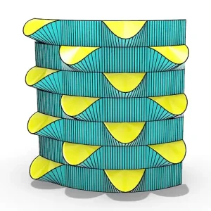
This is a complete 3D plane-faced polyhedron which projects down onto the form diagram. This polyhedron, , has a dual polyhedron, , defined by a node in one mapping to a plane in the other and a plane in one mapping to a node in the other.
The duality maps a point (, , ) to the dual plane = α + β − . This is called the pole and polar plane and is a part of projective geometry which was well understood in the 19th century.

The projection of the dual polyhedron, , onto the horizontal plane is the force diagram. This is known as the Maxwell reciprocal diagram and a line in the form diagram has a corresponding perpendicular line in the force diagram whose length is the force in the bar. The concepts of 2D reciprocal diagrams can be taken to 3D with 4D Rankine stress functions and beyond into ndimensions.

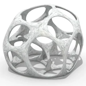
Plane-faced gridshells can also be described as polyhedrons. Taking the established 2D graphic statics methodology, it is possible to consider 2.5D shells and gridshells with the introduction of the slope diagram.
Gridshells have already been studied using graphic statics; thrust network analysis uses 2D graphic statics in the design of masonry shells and 3D Rankine reciprocals have been used to consider 3D space structures, including gridshells, but have struggled to find common usage due to the Rankine incompleteness problem.
String Art Generator by Yiran is a grasshopper plugin which generates a string art sequence based on an input image. You can

This paper by Alessandro Liuti, Sofia Colabella, and Alberto Pugnale, presents the construction of Airshell, a small timber gridshell prototype erected by employing a pneumatic formwork.

In this paper by Gregory Charles Quinn, Chris J K Williams, and Christoph Gengnagel, a detailed comparison is carried out between established as well as novel erection methods for strained grid shells by means of FE simulations and a 3D-scanned scaled physical model in order to evaluate key performance criteria such as bending stresses during erection and the distance between shell nodes and their spatial target geometry.

In this paper by Frederic Tayeb, Olivier Baverel, Jean-François Caron, Lionel du Peloux, ductility aspects of a light-weight composite gridshell are developed.