Spatial Deployment
On Elastic Geodesic Grids and Their Planar to Spatial Deployment
Stefan Pillwein1, Kurt Leiler1, Michael Birsak2, and Przemyslaw Musialski1,3
1Tu Wien
2Kaust
3NJIT
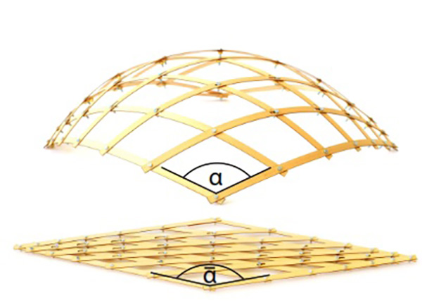
Fig. 1. A deployed elastic geodesic gridshell (top) and its planar lattice in the rest state (bottom) fabricated of wooden lamellas. The deployment of the whole kinematic system is based on changing angle α, such that α → α.
We propose a novel type of planar–to–spatial deployable structures that we call elastic geodesic grids. Our approach aims at the approximation of freeform surfaces with spatial grids of bent lamellas which can be deployed from a planar configuration using a simple kinematic mechanism.
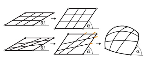
Fig. 2. The principle behind our planar to spatial deployment system. Top row: all members of a family are parallel and rigid, the kinematic linkage can move freely in the plane. Bottom row: non parallel layout produces a deadlock when trying to change the shape, inner members are too long. Allowing members to elastically deform, they buckle out of plane.
Such elastic structures are easy–to–fabricate and easy–to–deploy and approximate shapes which combine physics and aesthetics. We propose a solution based on networks of geodesic curves on target surfaces and we introduce a set of conditions and assumptions which can be closely met in practice.

Fig. 3. Overview of our approach and the notation. Left: the user selects four corners on a desired target surface. Center: the surface patch P with members of the д and h family. Each family is parameterized with pairs (u1, u2) and (v1, v2) respectively. Right: a corresponding planar patch P with corresponding members of the д and h family (cf. Section 3.2).
Our formulation allows for a purely geometric approach which avoids the necessity of numerical shape optimization by building on top of theoretical insights from differential geometry. We propose a solution for the design, computation, and physical simulation of elastic geodesic grids, and present several fabricated small-scale examples with varying complexity.
Moreover, we provide an empirical proof of our method by comparing the results to laser-scans of the fabricated models. Our method is intended as a form-finding tool for elastic gridshells in architecture and other creative disciplines and should give the designer an easy-to-handle way for the exploration of such structures.

Fig. 4. Shortest geodesics between point p and points on the opposite boundary (top) and distance fields emanating from p (bottom). Left: the peak area cannot be covered by shortest geodesics, cut locus L(p) and injectivity radius ir(p) are indicated. Right: Uncovered area sufficiently reduced by smoothing (cf. Section 3.3)
Design and construction of structures composed of curved elastic elements has a long history in the field of architecture. Alongside their aesthetical aspects imposed by nature, they have a lot of functional advantages: they are compact, lightweight and easy to build; nonetheless practicable, durable, and of high structural performance.
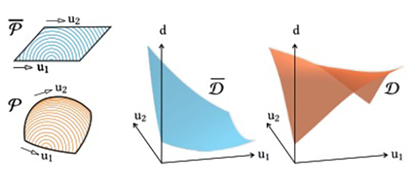
Fig. 5. Distance fields on a planar patch P and a surface patch P, computed from a single point shown on the left. By sampling all point-pairs along corresponding (u1, u2)-domains, we create distance maps Du (u1, u2) and Du (u1, u2, α). Note that the planar distance map D also depends on the shape of P and thus the angle α (cf. Section 4.2).
They have been utilized for a long time dating back to ancient vernacular architecture for formal as well as for performance reasons, however, the possibilities of their form-finding in the past were limited.
Fortunately, the currently available computational capabilities and advances in computer science open up avenues for direct modeling of complex shapes composed of elastically bending members. This goes beyond traditional architectural design and allows to aim at many general purpose products composed of such elements.
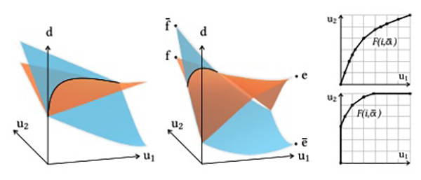
Fig. 6. Intersection of distance map Du (u1, u2, α) for planar patch in blue and distance map Du (u1, u2) for surface patch in orange. Left: proper intersection, fulfilling the constraints (cf. Sec. 4.3). Center: partial intersection, providing an invalid cladding function Fu . Right: piecewise linear functions Fu of both cases evaluated on a discrete grid (cf. Section 4.3).
The range of potential objects encompasses gridshells, formwork, paneling, various types of furniture, sun and rain protectors, pavilions and similar small-scale buildings, home decoration and accessories, like vases, bowls, or lamps, etc., and finally, also elements of future’s functional digital fabrics that can be utilized in engineering as well as in fashion.

Fig. 7. The influence of α on the cladding with grid members: its choice affects the distribution and coverage of the members д and h on the surface patch P. Right: the shape of the cladding function Fu with indicated members (cf. Section 4.3). Please note also the angles β and γ , which are used to determine minimum distances between lamellas with a certain width (cf. Section 4.4).
This vision leads directly to the objective of this paper: a designer provides a target surface and a computational method finds a planar grid of flat lamellas, that—when deployed—approximates the surface well. Figure 1 shows a planar and a deployed grid of wooden strips, where a surface with the curved lamellas being tangential to it can be imagined.
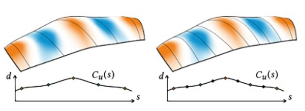
Fig. 8. One iteration of the member placement procedure. Left: members placed based on geometric features. Right: additional members placed in the gaps and distributed without affecting the initial members. Bottom row depicts the C-function with indicated members (cf. Section 4.4).
The joints between the lamellas allow for rotation and partially also for sliding. As the lamellas connecting opposite edges of the planar boundary quadrilateral are not parallel to each other, the grid is rigid in the plane. Given the flexibility of wooden lamellas with regard to bending and twisting, the grid is not rigid in space.
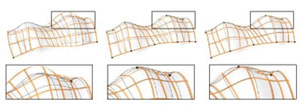
Fig. 10. The influence of anchors and notches on the example Archway. Left: Anchors at the corners are not sufficient to push the grid into the right configuration. Center: Deployed state without notches, local buckling and irregularities in smoothness can be observed. Right: Notches relax the structure to a more natural, lower energy shape (cf. Sections 4.5 and 4.6).
By adjusting only one degree of freedom, for example the angle α → α at one corner, the planar kinematic configuration elastically bends continuously into a spatial gridshell which approximates the desired surface. The deployment process is governed by the rules of physics, seeing the lamellas as thin elastic minimal energy beams, allowed to bend as well as to rotate and slide at their intersections.

Fig. 11. The effect of the weighting parameter µ in Ep (from left to right): surface shaded with K and geodesics; µ = 0.01, rods slide onto geodesics; µ = 0.1, sliding in high K areas reduced (our setting); µ = 1, sliding is heavily reduced. Refer to Section 7.3 for a further discussion on µ.
Our goal is to find a suitable planar setup of the lamellas that can be deformed into a spatial grid, fitting the target surface as closely as possible. To achieve this goal, we propose a solution based on networks of geodesic curves on the target surface.

Fig. 12. Comparison of the simulation result (Section 5) to a laser scan of the example Double Vault. The figure shows the point cloud with simulation results overlayed. The notches are indicated in red. The lamellas have cross section of 0.1 : 1.0 cm. The color indicates the L 2 distances of the points to the lamellas. The total RMS error of the comparison is 0.06 cm.
We introduce a set of conditions and assumptions which can be met closely in practice and restrict the grids to geodesics. However, at the same time, it allows us to develop a purely geometric solution which builds on top of theoretical background from differential geometry.
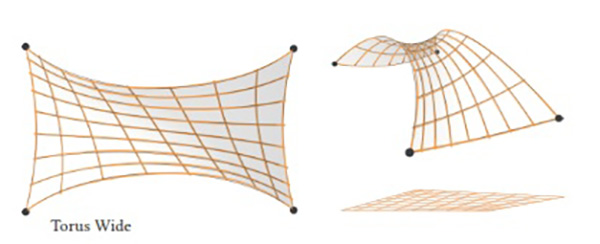
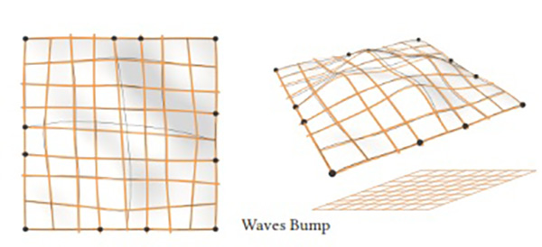
Fig. 13. Computed and simulated results without make, renderings of the simulation and the planar grid. The orange lines follow our simulation with notches. The dark lines follow the shortest geodesics on P.
Elastically Deployable Surfaces. An interesting way to deploy surfaces is to utilize the energy stored in planar configurations in order to approximate shapes, for instance using prestressed latex membranes in order to actuate precomputed planar geometric structures into freeform shapes, or to predefine flexible micro-structures which deform to desired shapes if set under tension.
A combination of flexible rods and prestressed membranes lead to Kirchhoff-Plateau surfaces that allow easy planar fabrication and deployment. These methods achieve their planar-to-spatial configuration from elastic tension in the network, either due to prestressing in the planar state or by setting appropriate boundary conditions.
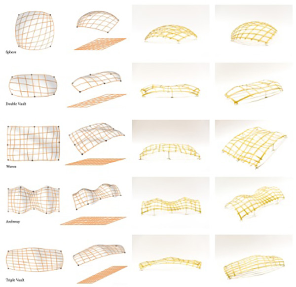
Fig. 14. Computed, simulated, and fabricated results of our method. Left: computed planar grids and renderings of the simulation. The orange strips follow our simulation with notches, the dark lines follow the shortest geodesics on P. Right: photographs of our makes. Best seen in the electronic version in closeup.
The latter approach is more closely related to ours, however, instead of structure optmization, we build on top of the differential geometric properties of geodesic curves on the target surfaces. Thus, our method is based on the assumption that the elastic elements can bend and twist, but not stretch and must therefore maintain the same length in the planar as well as in the spatial configuration.
Elastic geodesic grids can only approximate surfaces, that are “claddable” by unique shortest geodesics. If this is not the case, our smoothing algorithm ensures cladding, but surface details could be lost. Also the number and the density of members influences the representable shapes.
If the shape is of very high frequency geometric details, it might not be representable by a too sparse network of physical members. In turn, in order to ensure fabricability, only a limited number of members is possible. This relationship is an interesting issue for future work.





Comments