
Actively Bent Grid Shells
Form finding and structural analysis of actively bent timber grid shells
B. D’Amico, A. Kermani, H. Zhang
Centre for Timber Engineering (CTE), School of Engineering and the Built Environment, Edinburgh Napier University, Edinburgh, UK
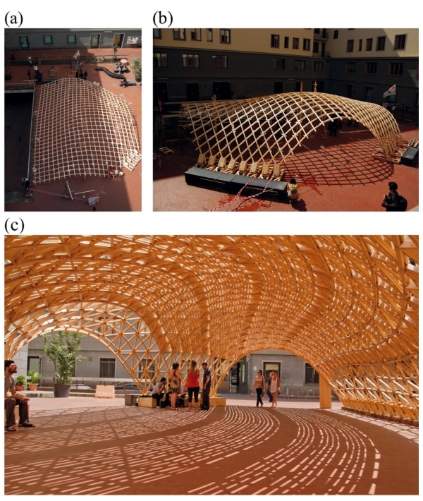
Figure 1: Toledo timber grid shell in Naples, Italy 2012: (a) Initial flat mat; (b) Forming process; (c) Complete structure.
Grid shells are efficient structural systems covering large open spaces with relatively small amount of materials. Also, post forming techniques allow realization of geometrically complex (free-form) shapes by means of standard connection systems.
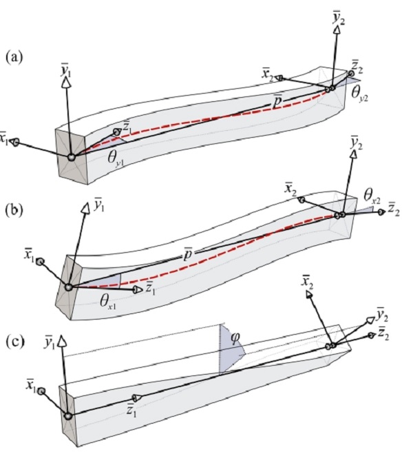
Figure 2: Element’s local displacements according to the orientation of the ends’ coordinate systems: (a) Rotations around the local ¯y axes; (b) Rotations around the local ¯x axes; (c) Angle of twist; The dashed line represents the element’s cubic shape function.
However, due to complexity of the analysis-design process, they are rarely utilized in construction design. In this paper, a ‘facilitating’ numerical framework is introduced in which, for a given continuous reference shape, a geometrically similar discrete model is found by implementation of a six degree of freedom formulation of the Dynamic Relaxation method, to handle members bending and torsional stiffness.
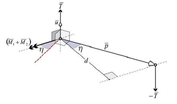
Figure 3: Shear reaction force T¯ at the element’s end nodes.
A grid cutting pattern algorithm is introduced, as well as methods to numerically simulate the double-layer construction technique and a novel (singlenode) cylindrical joint model.
The methods are extensively tested and validated on a range of structures, from ‘simple’ single-rod cases to more complex, actively bent, grid shell frameworks.

Figure 4: Slotted hole connection system [4]: (a) Schematic view; (b) Two distinct N and M connectivity lists are used to define the equivalent numerical model.
Free-form grid-shell structures can be formed by connecting short straight beam elements together into nodes thus converting a curved continuous surface in a faceted shell.
From a geometrical point of view, the described process deals with complex connection systems: Each element converges to the node of the grid at a different angle, thus non-standard connections (and Computer-Aided Manufacturing process) become inevitable.
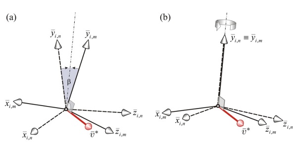
Figure 5: Local coord. systems of the surrounding n and m elements at node i: (a) Spherical hinge. The rotations of the two systems are decoupled; (b) Cylindrical joint. The ¯yi,n and ¯yi,m local axes are constrained along the same direction.
A ‘low-tech’ method for building free-form structures using standard (bolted/screwed) connection systems is by bending initially flat elastic rods, such as solid timber planks/laths, to form actual continuous curves.
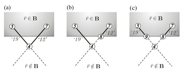
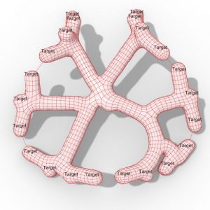
Figure 7: Cutting algorithm: (a) Two elements crossing the subspace B are connected to the same node 4; (b) At the 12th iteration the end node of element ‘12’ is updated, while element ‘19’ remains linked to node 4; (c) The boundary node 9 can be (independently) computed at the 19th iteration.
For timber grid shells made of continuous bending members, two subcategories can be defined differentiating on the geometric parameters assigned to generate a grid on a surface: If screwed laminated timber ribs are arranged following geodesic patterns (shortest curve on a surface for two given points) the planks composing the rib will only be subjected to torsion and bending around the weak axis enhancing the ‘allowable’ width of the the plank’s cross section.
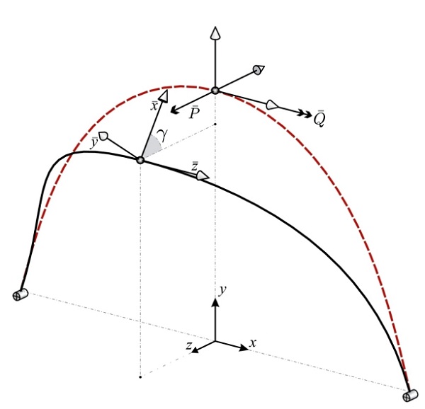
Figure 10: Combined bending and torsion numerical tests set up: Displacements y, z and rot. angle γ of the midspan node for different P¯-Q¯ values are reported in Tab.
This technique was used for the construction of the Hannover Expo pavilion. A different approach was adopted in the design of the Mannheim timber grid shell for the Garden Festival.
In this case, it was assumed a constant distance (50mm) between the consecutive nodes belonging to the same rib, which was built-up with two overlapping laths (double layer technique).
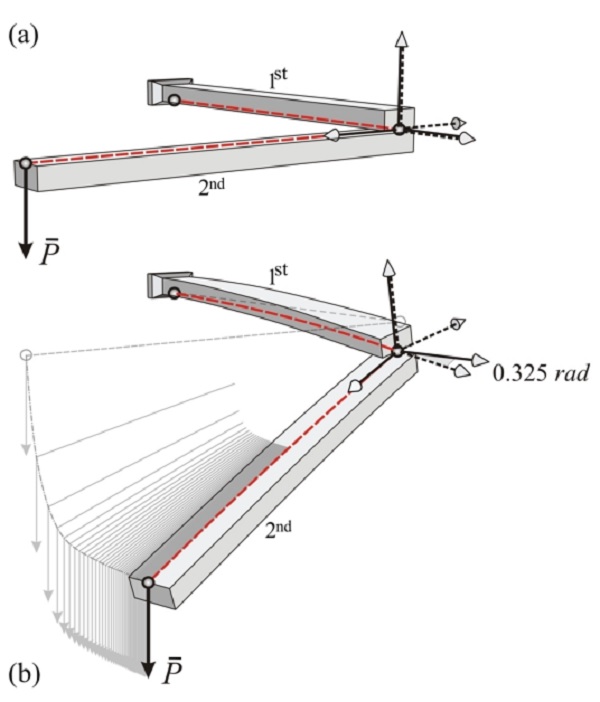
Figure 11: Cylindrical joint numerical test: (a) Unloaded configuration; (b) Final configuration.
Accordingly, the resulting mesh geometry of the grid shell did not follow the geodesic paths (thus, lateral bending occurs as well).
However, this second design approach allowed the possibility of assembling the grid shell laid out flat (as a two-way mat of straight continuous rods) and eventually post forming it in a double curved geometry by imposing external displacements under the form of temporary crane-cable systems or adjustable scaffolding.
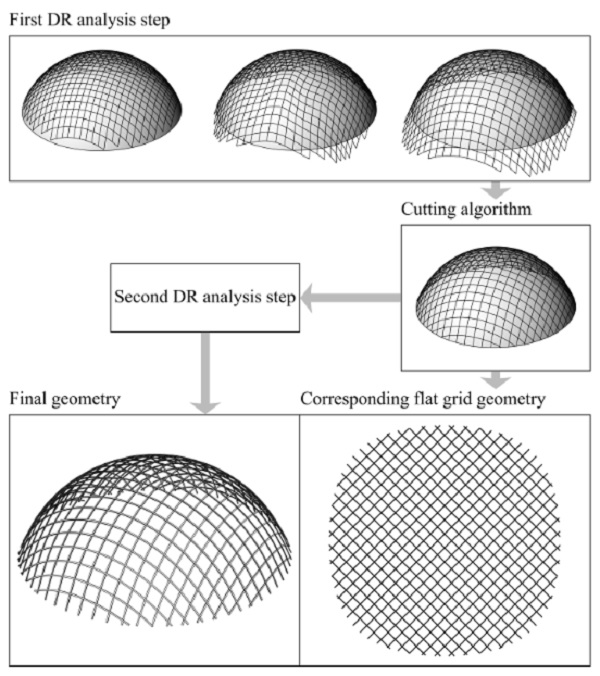
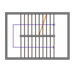
Figure 12: Form finding of a grid shell dome: Flowchart.
With the main grid eventually formed, additional bracing elements can be added to the system enhancing the in-plane shear stiffness of the equivalent shell. The terms post formed, actively or elastically bent are usually used to describe such kind of grid shell structures.
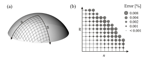
Figure 13: Spherical cap: (a) Chebyshev net found by Eqs; (b) Comparison of DR output with the Chebyshev net geometry.
The work presented in this paper has aimed to facilitate the design of actively bent grid shells, with particular attention on the use of timber.
A numerical framework is developed to address a range of issues at various design stages, including, a viable form finding procedure, structural analysis and assembly definitions (flat mat geometry) by combining finite element procedures (Dynamic Relaxation) with numerical methods typical of the computational geometry (mesh manipulation and geometry intersection).
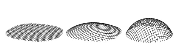
Figure 14: Spherical cap: Preliminary form finding analysis by Newton-Raphson method. Grid cutting pattern and final position of the boundary nodes are those obtained at DR completion of the first form finding step.
Further investigations, concerning the coupling of rotational degree of freedom, resulted in the development of a novel single-node numerical model for large rotation simulation of cylindrical joint systems.
In addition, a procedure is illustrated to allow changing the element’s crosssectional properties during the completion of the form finding stage by maintaining the corresponding ends reactions values.
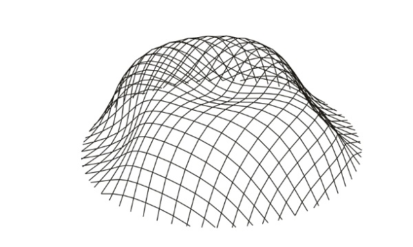
Figure 15: Load analysis of the grid shell dome: Deformed geometry obtained by DR method (scale – 30 times).
Such procedure permits load analyses in which the increase in stiffness of the built-up timber ribs (for effect of shear blocks insertion) is taken into account, and at the same time maintains the equilibrium configuration (previously) obtained without shear blocks.
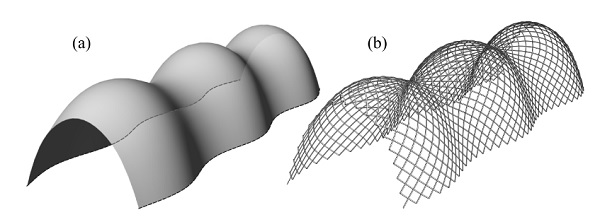
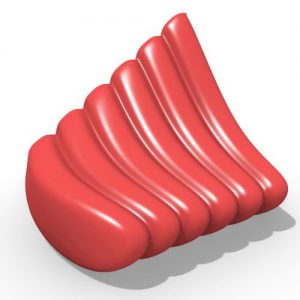
Figure 17: Corrugated barrel vault: (a) Reference surface; (b) Final geometry.
In order to allow the implementation of the described procedures, a detailed description of the equations involved is given.
After preliminary validation tests on ‘simple’ structural systems, the procedures are applied to the form finding, structural analysis and mat cutting patterns search of a grid shell dome, as well as the form finding analysis of a corrugated barrel vault.
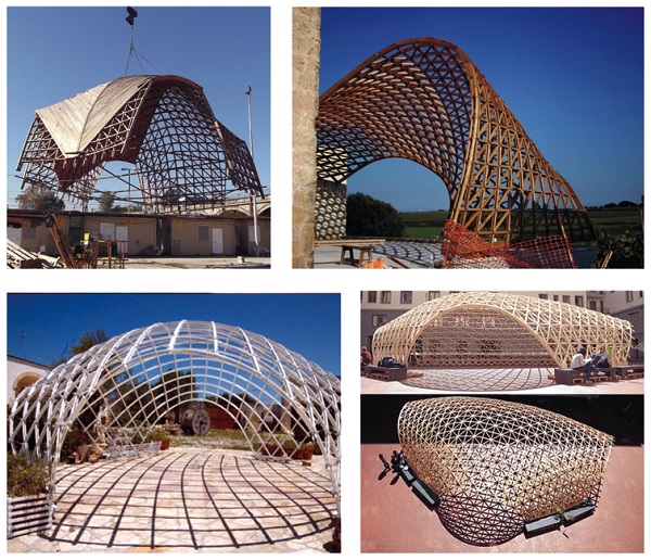
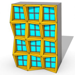
Figure 18: Post-formed timber grid shells.
The accompanying numerical tests demonstrated the reliability of the proposed method. The preliminary tests showed a good level of accuracy for the six DoF DR formulation in the estimation of the load-displacements functions.
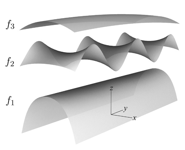
Figure A.1: Corrugated barrel vault: f(¯r) = f1 + f2 + f3 + c.
Accordingly, the six DoF DR can be used for non-linear buckling analyses at the completion of the form finding routine, thus allowing to take into account the effect of pre-stress (and material relaxation) on the final load bearing capacity.


Comments